

Composite polymer electrolyte membrane for polymer electrolyte membrane fuel cells
a technology of electrolyte membrane and fuel cell, which is applied in the direction of non-aqueous electrolyte cells, cell components, electrochemical generators, etc., can solve the problems of low conductivity and brittleness of the membrane, forestalization of the commercialization of the polymer electrolyte membrane fuel cell, and high cost of fluorinated polymer materials. , to achieve the effect of reducing cos
- Summary
- Abstract
- Description
- Claims
- Application Information
AI Technical Summary
Benefits of technology
Problems solved by technology
Method used
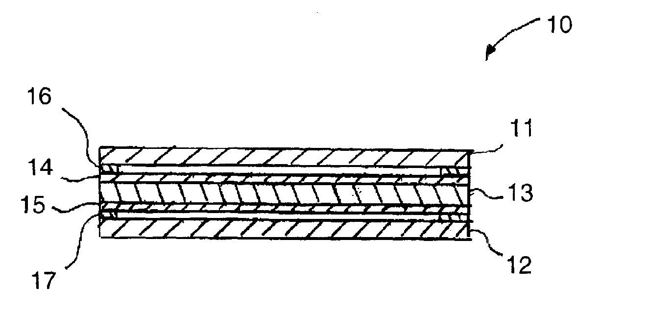
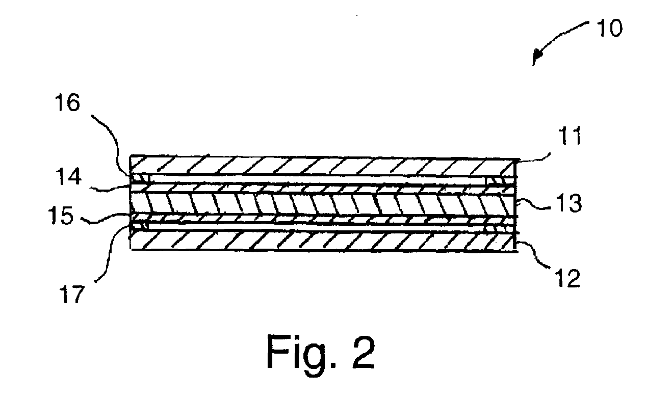
Image

Examples
example 1
[0040]In this example, to examine the stability of the water-based resin of this invention under fuel cell operating conditions, the water-based resin was first mixed with a NAFION emulsion to form a membrane. FIG. 4 shows the results of a lifetime test of a polymer electrolyte membrane fuel cell with a composite membrane in accordance with one embodiment of this invention comprising the water-based resin (80% by weight) and NAFION emulsion (20% by weight). The performance of the cell, as is shown, is very stable although the cell performance is low due to low NAFION doping. The thickness of the membrane was approximately 5 mils. NAFION was used in this example as an expedient to form a membrane for initial testing of the stability of the water-based resin. However, it is not needed in the membrane manufacturing.
example 2
[0041]In this example, the water-based resin (34% by weight) was mixed with polymethyl vinyl ether maleic acid (33% by weight) and sulfuric acid (33 % by weight) to produce a membrane. The thickness of the membrane was approximately 5 mils. The strength of the membrane was found to increase after the addition of the 33% by weight sulfuric acid. However, it should be noted that too much sulfuric acid weakens the membrane. FIG. 5 shows the results of a lifetime test of the membrane.
example 3
[0042]In this example, the water-based resin (40% by weight) was mixed with SiO2 (15% by weight) and phosphoric acid (45% by weight) to produce a membrane. The thickness of the membrane was approximately 5 mils. The silica in the membrane acts as a wetting agent for holding water so as to promote proton conductivity. In accordance with one preferred embodiment of this invention, the amount of silica utilized in the membrane is in the range of about 10% to about 40% by weight of the membrane. FIG. 6 displays the performance curves of a fuel cell with the membrane. Although the performance is low, modification of the catalyst layer, reductions in the thickness of the membrane, and increasing acid doping can be expected to improve performance.
[0043]FIG. 7 shows the results of a thermal gravity analysis (TGA) on a membrane in accordance with this invention. The results indicate that the membrane can be operated at greater than 140° C. The boiling point of the phosphoric acid is 158° C. ...
PUM
| Property | Measurement | Unit |
|---|---|---|
| Temperature | aaaaa | aaaaa |
| Temperature | aaaaa | aaaaa |
| Acidity | aaaaa | aaaaa |
Abstract
Description
Claims
Application Information