Piezo-electric tag

a technology of piezoelectric and electrode, applied in piezoelectric/electrostrictive device details, instruments, therapy, etc., can solve the problem that the radiation level rarely represents any health and safety risk, and achieve the effect of low current consumption and high gain

Inactive Publication Date: 2005-05-17
LIBERTY PATENTS LLC +1
View PDF20 Cites 62 Cited by
  • Summary
  • Abstract
  • Description
  • Claims
  • Application Information

AI Technical Summary

Benefits of technology

[0014]The invention provides the advantage that the vibrating means is capable of providing voltage magnification, thereby enabling the tag to be powered from radiation incident thereupon.
[0035]Conveniently, the tag is arranged such that the receiving means incorporates first and second antennae for generating the received signal for exciting the vibrating means, the first antenna adapted to respond to microwave radiation and the second antenna adapted to respond to radiation having a carrier frequency corresponding to a resonant frequency of the vibrating means. Incorporation of two antennae for generating the received signal provides the advantage that the tag is powerable from radiation having a number of possible carrier frequencies.

Problems solved by technology

Such moderate levels of radiation rarely represent any health and safety risk.

Method used


Image

  • Piezo-electric tag
  • Piezo-electric tag
  • Piezo-electric tag

Examples


first embodiment

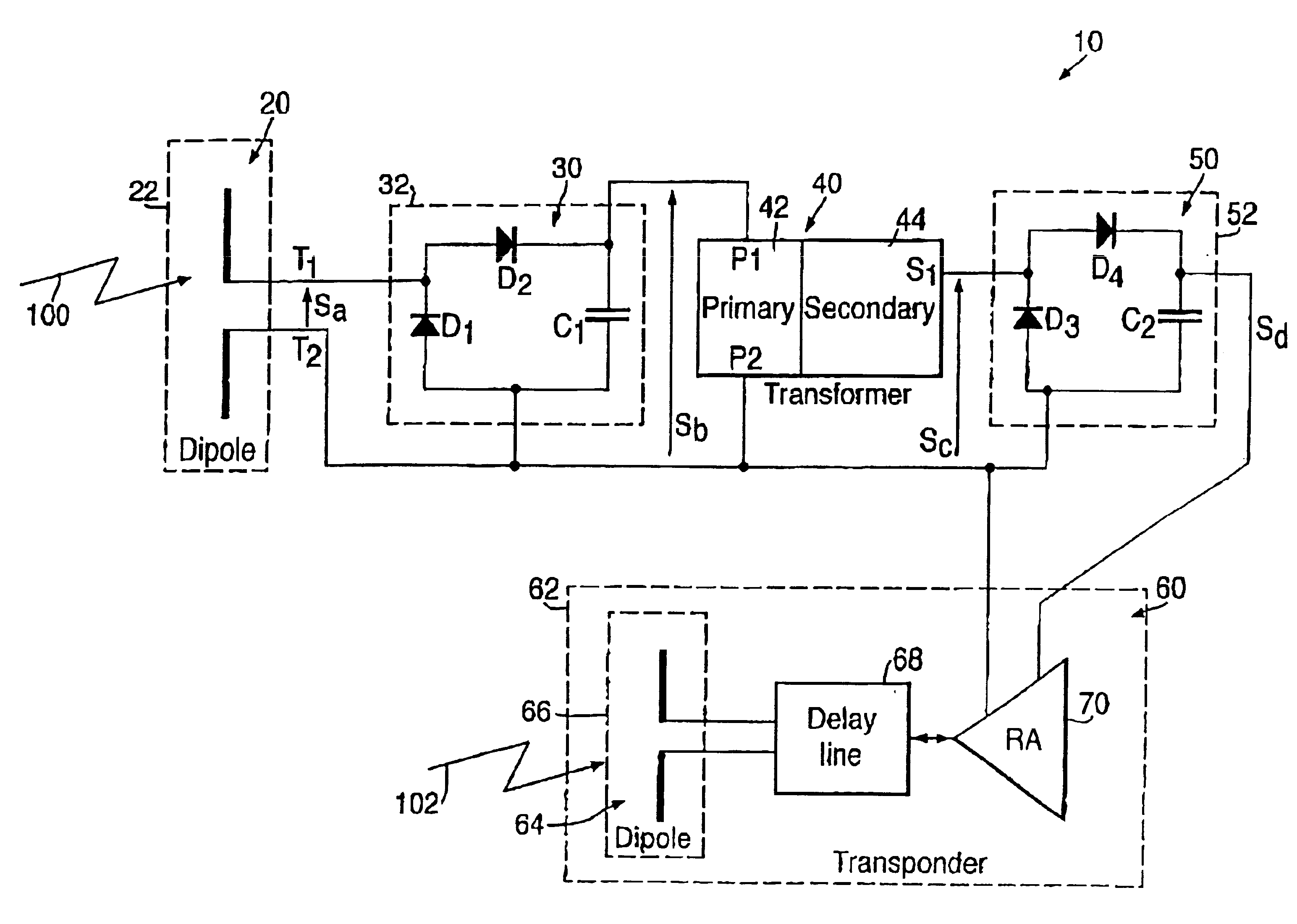
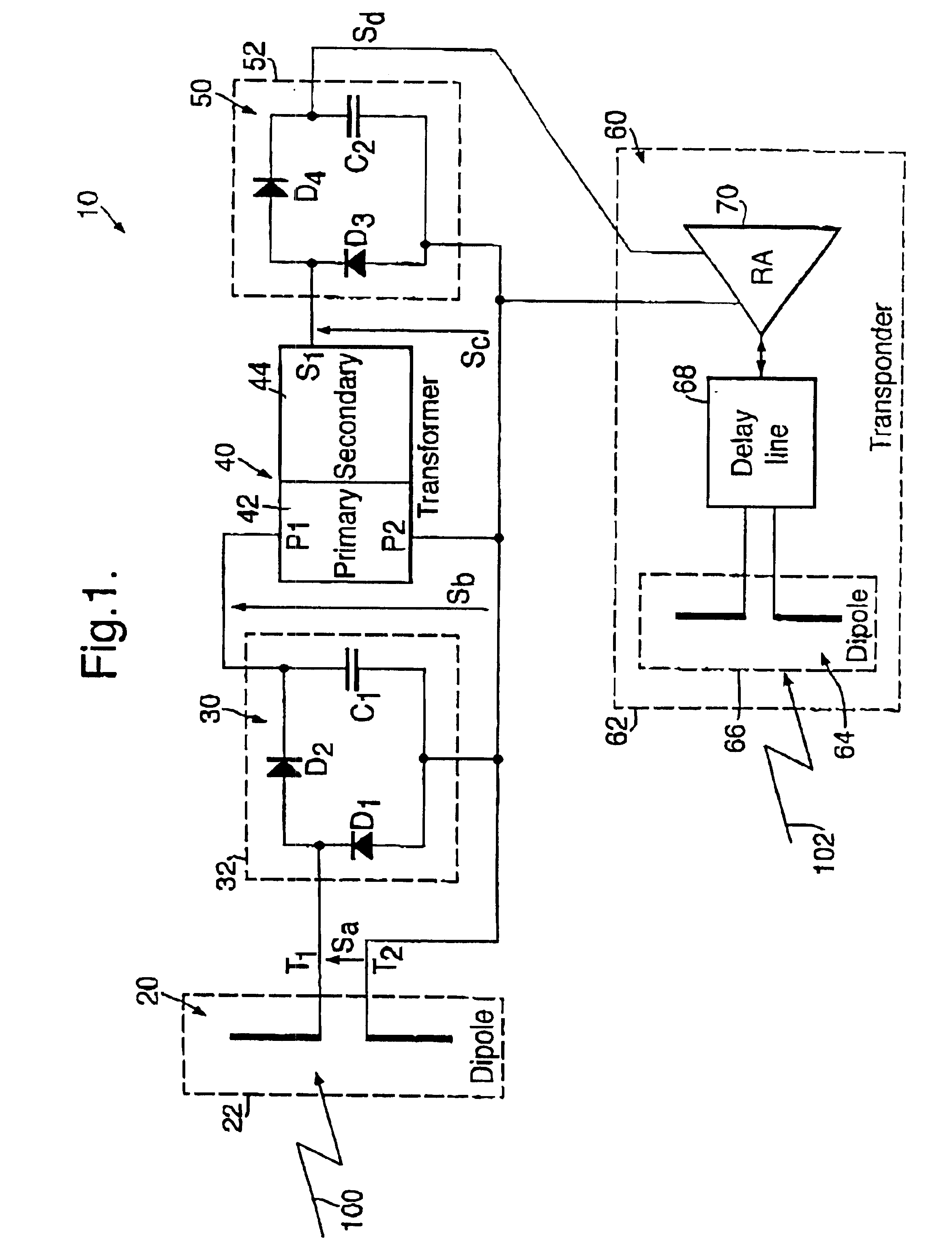
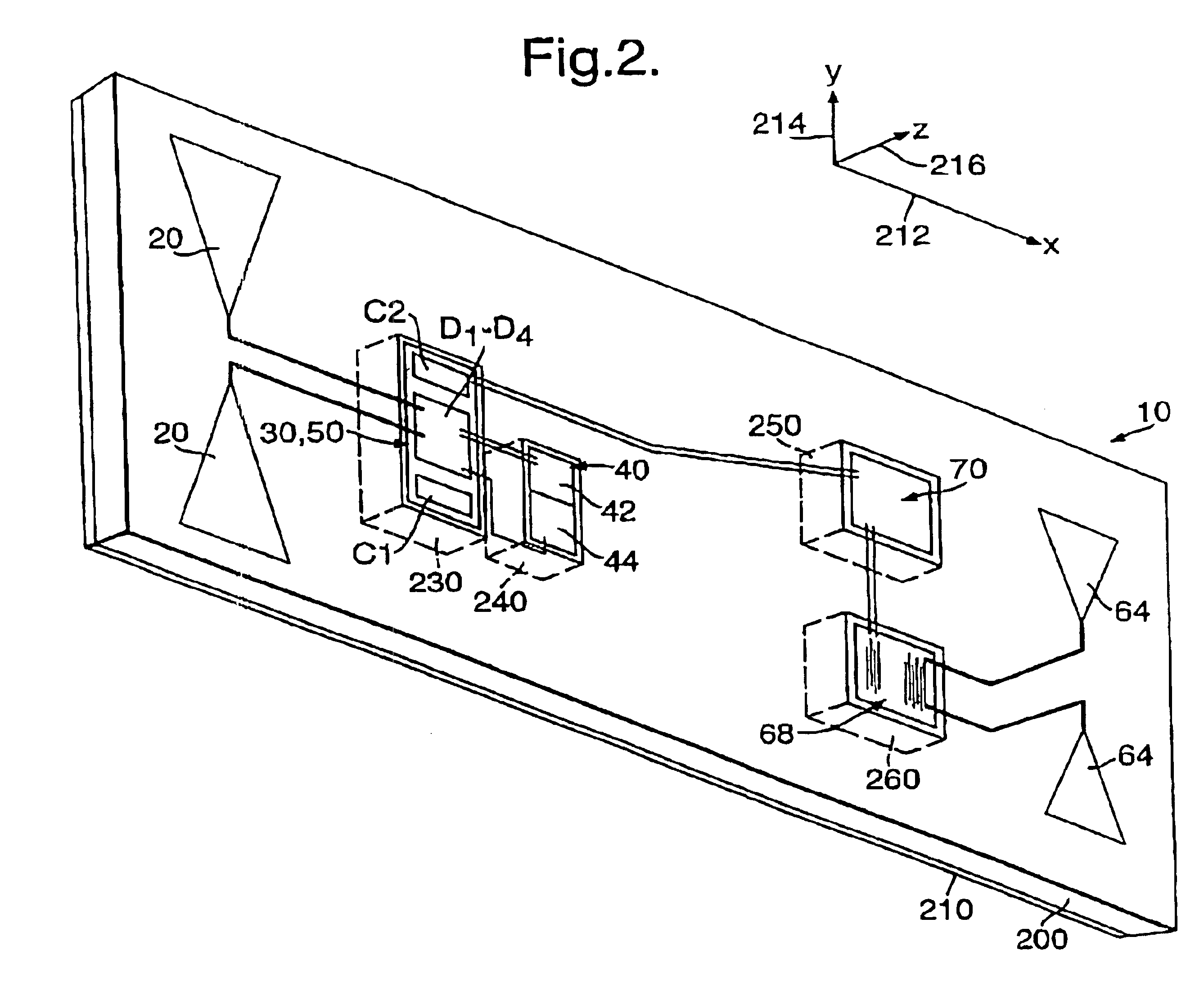
[0048]Referring to FIG. 1, there is shown a piezo-electric tag according to the invention indicated by 10. The tag 10 incorporates a number of sections, namely a first dipole antenna indicated by 20 and included within a dotted line 22, a first rectification circuit indicated by 30 and included within a dotted line 32, a piezoelectric transformer indicated by 40 incorporating a primary region 42 and a secondary region 44, a second rectification circuit indicated by 50 and included within a dotted line 52, and a transponder circuit indicated by 60 and included within a dotted line 62. The sections are incorporated into a plastic card having external dimensions of 55 mm width, 85 mm length and 1 mm thickness; this will be further described later with reference to FIG. 2.

[0049]The transponder 60 incorporates a dipole antenna indicated by 64 and included within a dotted line 66, a bi-directional surface acoustic wave (SAW) delay line 68 and a reflection amplifier 70.

[0050]The first dipo...

second embodiment

[0068]Referring now to FIG. 3, there is shown a piezoelectric tag according to the invention indicated by 300. The tag 300 is identical to the tag 10 except that it additionally includes a planar coil 310 in parallel connection with the capacitor C1.

[0069]The earth plane layer 210 can be selectively absent in a vicinity of the coil 310 so as not to excessively screen the coil 310. The coil 310 is formed onto the second major face of the layer 200 shown in FIG. 2 adjacent to the circuits 30, 50 and the transformer 40. The capacitor C1, in parallel with an electrical capacitance presented by the transformer 40 between its terminals P1, P2, and the coil 310 are operable to parallel resonate at the resonant frequency of the transformer 40, namely 300 kHz. Inclusion of the coil 310 enables the tag 300 to be powered not only from 1 GHz radiation received at the antenna 20 but also from inductively coupled magnetic fields at 300 kHz coupling to the coil 310. The tag 300 can thereby be powe...


PUM


Abstract

A piezo-electric tag in the form of a card has a first dipole antenna, a first rectification circuit, a piezo-electric transformer, a second rectification circuit, and a transponder circuit. In operation, the antenna receives incoming radiation and generates a corresponding signal which propagates to the first circuit which demodulates and filters it to generate a signal which is applied to the transformer to excite it. The transformer increases the voltage amplitude of the signal by generating a relatively higher voltage amplitude signal which is used in the tag to generate a signal for supplying power to the transponder. The transformer provides voltage magnitude enhancement to generate potentials suitable for operating active electronic circuits incorporated into the tag. The tag can be personnel wearable and even adapted for permanent inclusion into biological systems.

Description

[0001]This application is a 371 national stage entry of PCT / GB00 / 02944 dated Jul. 31, 2000, which claims priority to United Kingdom application 9917856.8 dated Jul. 29, 1999.[0002]The present invention relates to a piezo-electric tag.BACKGROUND OF THE INVENTION[0003]Tags are portable devices which are capable of being attached to items or personnel wearable. They can be used, for example, for remotely identifying the items or receiving information therefrom. In many applications, the tags must be compact and be capable of responding after long periods of inactivity, for example where the tags are incorporated into items placed into storage for periods of several years.[0004]Conventionally, tags can be passive devices which modify and reflect interrogating radiation directed thereto from associated interrogating sources. Because the tags do not provide power gain, their operating range from the sources is often limited to a few meters.[0005]Active tags are known which incorporate onb...

Claims


Application Information

Patent Timeline
Patent Type & Authority Patents(United States)
IPC IPC(8): A61N1/378A61N1/372G08B13/24G06K19/067H01L41/107A61B5/00G01S13/02G01S13/74G06K19/07G06K19/077G08G1/00H01L41/04H02J17/00H04B1/59
CPCG06K19/067G06K19/0675H01L41/107H01L41/044G06K19/0723H10N30/804H10N30/40
Inventor FORSTER, IAN J
Owner LIBERTY PATENTS LLC
Why Eureka
Try Eureka