Road surface detection apparatus and apparatus for detecting upward/downward axis displacement of vehicle-mounted radar

a detection apparatus and vehicle-mounted technology, applied in the direction of process and machine control, using reradiation, instruments, etc., can solve the problems of wheel tire speed not necessarily agreeing with vehicle speed, and the detection range of radar becoming shorter

Inactive Publication Date: 2005-05-24
FUJITSU GENERAL LTD
View PDF19 Cites 27 Cited by
  • Summary
  • Abstract
  • Description
  • Claims
  • Application Information

AI Technical Summary

Benefits of technology

[0010]The present invention has been devised in view of the above problem, and an object of the invention is to provide an apparatus for detecting, in a simple and accurate manner, an upward / downward axis displacement which is a major concern in an automotive radar.
[0018]According to a sixth aspect of the present invention, preferably, the road surface detection apparatus further includes gradient detecting means for detecting the gradient of the road on which the vehicle is traveling wherein, when performing the axis displacement determination, the axis displacement determining means compares the reception level detected by the road surface signal detecting means with the reference level after correcting the reception level based on the gradient of the road detected by the gradient detecting means. By so doing, the axial displacement determination in a sloping road section can be performed correctly.

Problems solved by technology

However, if slip occurs between a wheel and the ground, the wheel speed does not necessarily agree with the vehicle speed.
For example, in the case of a construction machine such as a power shovel, since tires can easily spin, the tire speed does not necessarily agree with the vehicle speed.
If the radar axis is displaced, there occurs the problem that the detection range of the radar becomes shorter.
However, an apparatus for detecting such an axis displacement in a simple and accurate manner has not been available up to this date.

Method used


Image

  • Road surface detection apparatus and apparatus for detecting upward/downward axis displacement of vehicle-mounted radar
  • Road surface detection apparatus and apparatus for detecting upward/downward axis displacement of vehicle-mounted radar
  • Road surface detection apparatus and apparatus for detecting upward/downward axis displacement of vehicle-mounted radar

Examples


Embodiment Construction

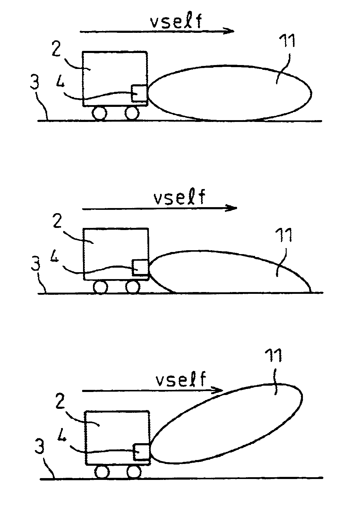
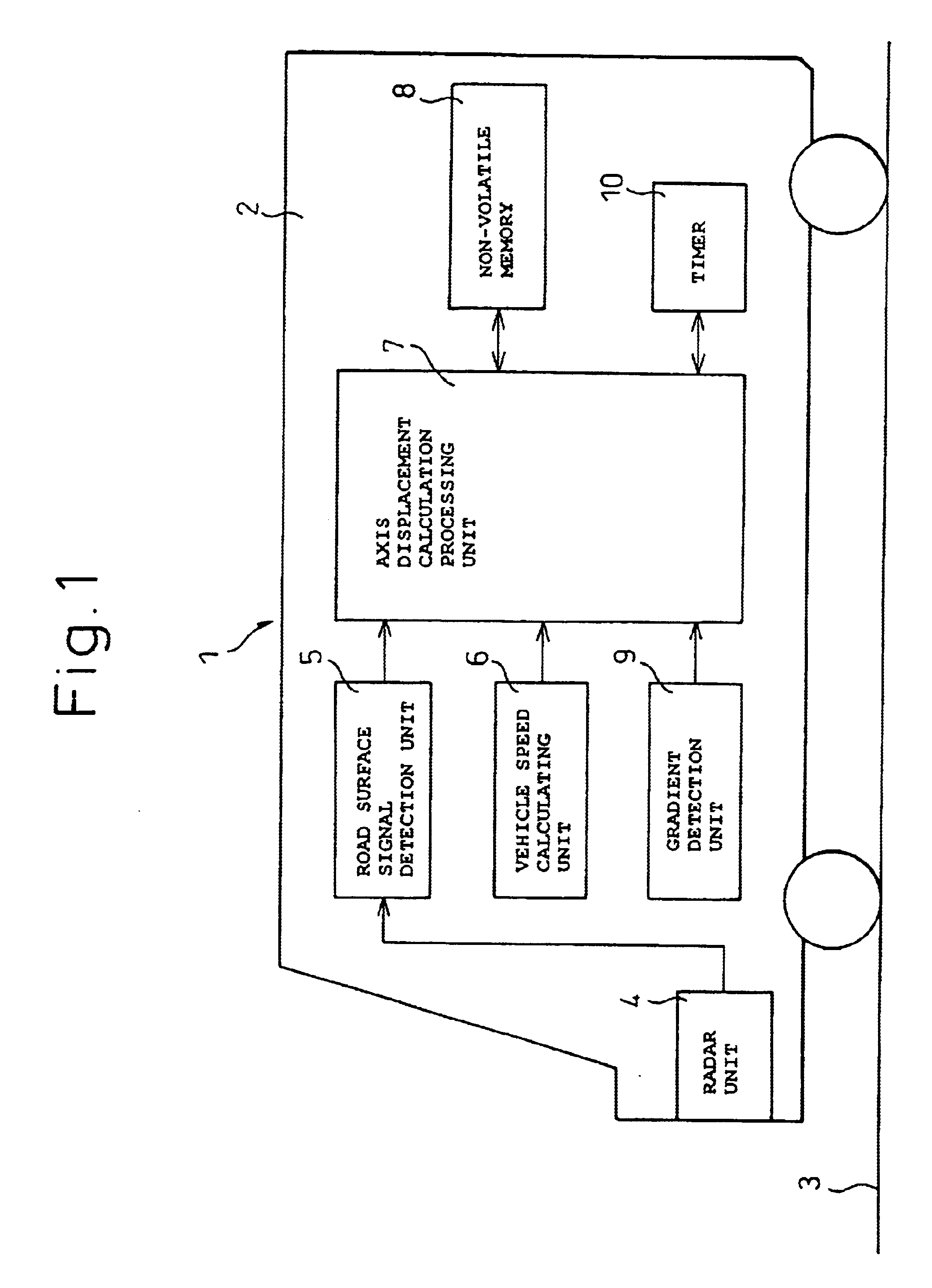
[0038]FIG. 1 is a diagram schematically showing the configuration of a road surface detection apparatus 1 according to one embodiment of the present invention. The road surface detection apparatus 1 is mounted on a vehicle 2, and detects the road surface 3 on which the vehicle 2 is traveling by projecting a radar beam from a radar unit 4 onto the road surface. When a radar beam, for example, an electromagnetic wave in the millimeter band, is projected from the radar unit 4 via a highly directional antenna, the radar beam is scattered by the road surface 3, and signal components reflected in the direction opposite to the projection direction are received by a road surface signal detection unit 5 for detection of the road surface 3.

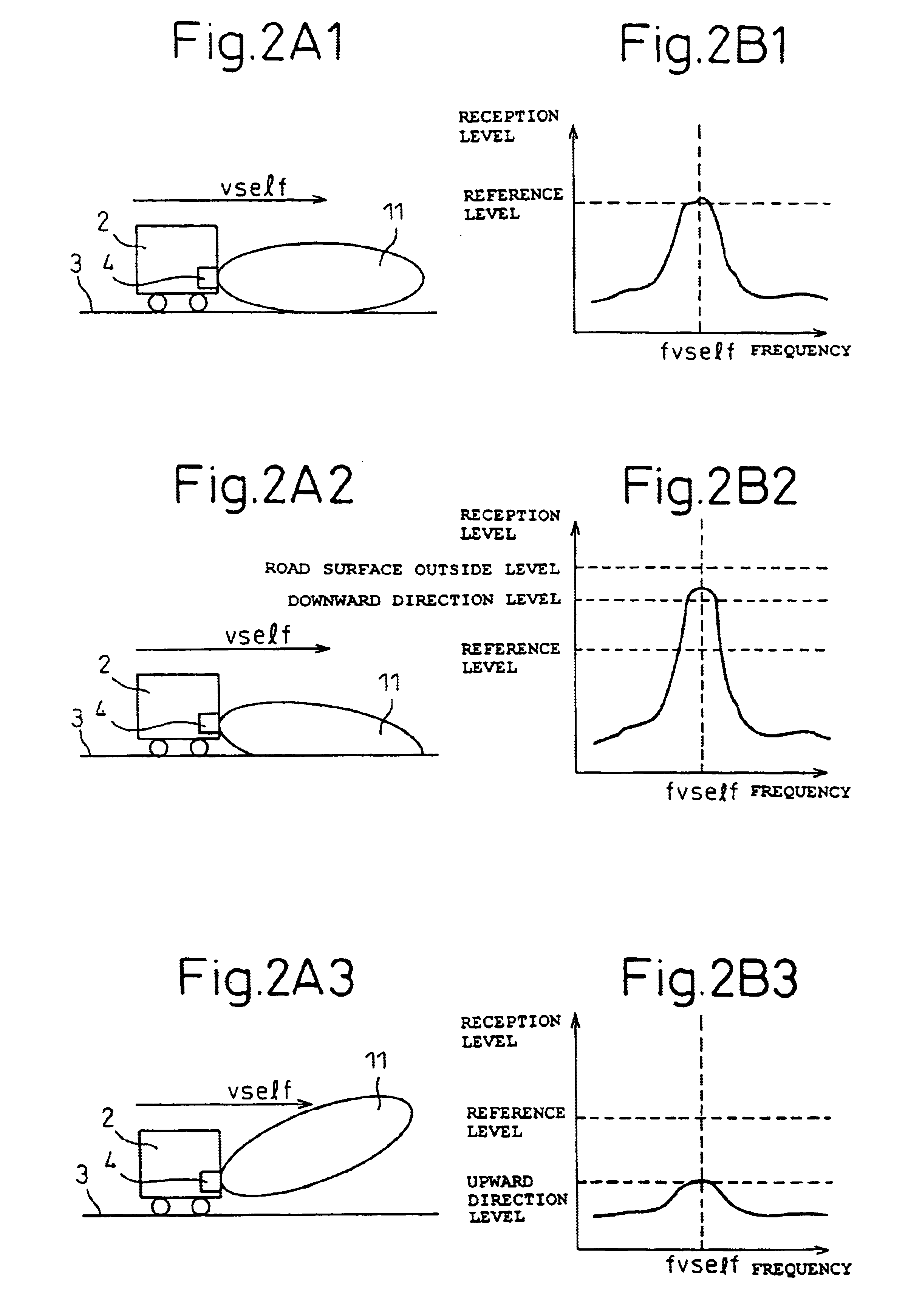
[0039]The road surface signal detection unit 5 detects the road surface by determining that, of the received signal components, the signal component that experienced a Doppler shift proportional to the traveling speed of the vehicle 2, which is calculated b...


PUM


Abstract

A road surface detection apparatus capable of detecting an upward / downward displacement in radar axis when detecting a road surface by projecting a radar beam. The apparatus projects a radar beam signal onto the road surface on which the radar-equipped vehicle is traveling, and receives a signal containing a reflected signal of the radar beam signal. Then, the apparatus compares the level of the road surface reflected signal contained in the received signal with a predetermined reference level and, if the result of the comparison lies outside a predefined range, then the apparatus determines that the axis defining the projection direction of the radar beam signal is displaced.

Description

CROSS-REFERENCE TO RELATED APPLICATION[0001]This application claims priority of International application number PCT / JP01 / 11302, filed Dec. 21, 2001, which in turn claims priority of Japanese application number 2000-398878, filed Dec. 27, 2000.TECHNICAL FIELD[0002]The present invention relates to a road surface detection apparatus for detecting, using a Doppler radar or the like, the road surface on which a vehicle is traveling. The invention also relates to an apparatus for detecting an axis displacement, in an upward or downward direction, of a radar mounted on a vehicle.BACKGROUND ART[0003]Heretofore, various kinds of radar systems have been developed for automotive applications and for such purposes as increasing vehicle driving safety. Automotive radar systems so far developed include those that use laser beams or ultrasonic waves, and those that use radio waves, especially millimeter waves in the wavelength region called the millimeter band, such as a frequency-modulated conti...

Claims


Application Information

Patent Timeline
Patent Type & Authority Patents(United States)
IPC IPC(8): G01S13/60G01S13/93G01S13/88G01S13/00G01S7/02G01S7/41B60K31/00G01S7/40G01S7/292G01S13/931
CPCG01S7/4026G01S13/60G01S13/931B60K31/0008G01S2013/9375B60W2420/52B60W2540/12B60W2550/308G01S7/2922G01S7/2927G01S7/412G01S7/4972G01S7/52004G01S2007/4091G01S2007/4034G01S2013/9325G01S2013/9353B60W2050/0215G01S2013/932G01S2013/93271B60W2554/801G01S7/4034G01S7/4091G01S7/00
Inventor ASANUMA, HISATERUKISHIDA, MASAYUKI
Owner FUJITSU GENERAL LTD
Why Eureka
Try Eureka