Stent and catheter assembly and method for treating bifurcations

a technology which is applied in the field of stent and catheter assembly and the field of treating bifurcations, can solve the problems of stent failure to completely repair the bifurcated vessel, difficulty in repairing the bifurcated vessel, and blood flow in other parts of the bifurcation may be compromised

Inactive Publication Date: 2005-05-24
ABBOTT CARDIOVASCULAR
View PDF334 Cites 128 Cited by
  • Summary
  • Abstract
  • Description
  • Claims
  • Application Information

AI Technical Summary

Benefits of technology

[0017]A second stent is provided for implanting in the main vessel adjacent to a bifurcation in which a cylindrical member has distal and proximal ends and an outer wall surface therebetween, which can typically be similar to the outer wall surface of stents used in the coronary arteries. An aperture is formed in the outer wall surface of the apertured stent and is sized and positioned on the outer wall surface so that when the apertured stent is implanted in the main vessel, the aperture is aligned with the side-branch vessel and the proximal angled stent in the side-branch vessel, providing unrestricted blood flow from the main vessel through to the side-branch vessel. Deployment of the angled and apertured stents is accomplished by a novel stent delivery system adapted specifically for treating bifurcated vessels.
[0022]The present invention further includes a method for delivering the proximal angled and the main-vessel (apertured) stents in the bifurcated vessel. In a preferred embodiment of the side-branch catheter system (side-branch catheter plus proximal angled stent), the distal end of the tracking guide wire is advanced into the side-branch vessel and distal to the target area. The side-branch catheter is then advanced along the tracking guide wire until the distal end of the catheter is just proximal of entering the side-branch. The distal end of the integrated, stent-positioning guide wire is then advanced by the physician pushing the guide wire from outside the body. The distal end of the stent-positioning wire travels through the positioning guide wire lumen and passes close to the proximal end of the proximal angled stent and expandable member and exits the lumen. The wire is advanced in the main vessel until the distal end is distal to the side-branch vessel. The catheter is then advanced into the side branch until resistance is felt from the stent-positioning guide wire pushing up against the ostium of the side-branch vessel causing the proximal angled stent to rotate into position and arresting its advancement at the ostium. Thereafter, the proximal angled stent, mounted on the expandable member, is aligned across the target area and the angled proximal end of the stent is aligned at the intersection of the side-branch vessel and the main vessel (the ostium of the side-branch vessel) so that the stent completely covers the target area in the side-branch vessel, yet does not extend into the main vessel, thereby blocking blood flow. The expandable member is expanded thereby expanding and implanting the proximal angled stent in the side-branch vessel. The positioning wire prevents forward movement of the expandable member and proximal angled stent during inflation. Thereafter, the expandable member is deflated and the side-branch catheter assembly is withdrawn from the patient in a known rapid-exchange manner. In this embodiment, the side-branch catheter is designed so that both the side-branch tracking guide wire and main-vessel positioning guide wire can be left in their respective vessels should sequential or simultaneous high pressure balloon inflation be required in each of the vessels in order to complete the stenting procedure. In other words, the integrated positioning wire can be unzipped from the proximal 100 cm of the catheter thereby allowing it to act as a rapid exchange wire. Preferably, high pressure balloons are inflated simultaneously in the main vessel and proximal angled stents in order to avoid deforming one stent by unopposed balloon inflation within the other one. This additional step of high pressure balloon inflation is a matter of physician choice. A further advantage of this embodiment is that by waiting to advance the integrated stent-positioning wire out of catheter only when the catheter distal end is near the target area, wire wrapping, encountered in an embodiment utilizing two non-integrated guide wires, is avoided. Utilizing this preferred method, the side-branch vessel can be stented without the need for stenting the main vessel.
[0025]Utilizing this preferred method, the main vessel can be stented without the need for stenting the side-branch vessel. An advantage of this embodiment is that a major side branch, not diseased and requiring treatment, exiting from a main vessel requiring stenting, may be protected by the positioning wire while the main vessel is stented. If “snowplowing” compromise or closure of the side-branch vessel occurs with main-vessel stenting, then access is already present and guaranteed for stenting of the side-branch vessel over the wire already in place in the manner described above. This will allow confident stenting of a main vessel segment containing a major side branch. In this usage, only if compromise or occlusion of the side branch occurs, will additional stenting of the side branch be required.

Problems solved by technology

Repair of vessels that are diseased at a bifurcation is particularly challenging since the stent must overlay the entire diseased area at the bifurcation, yet not itself compromise blood flow.
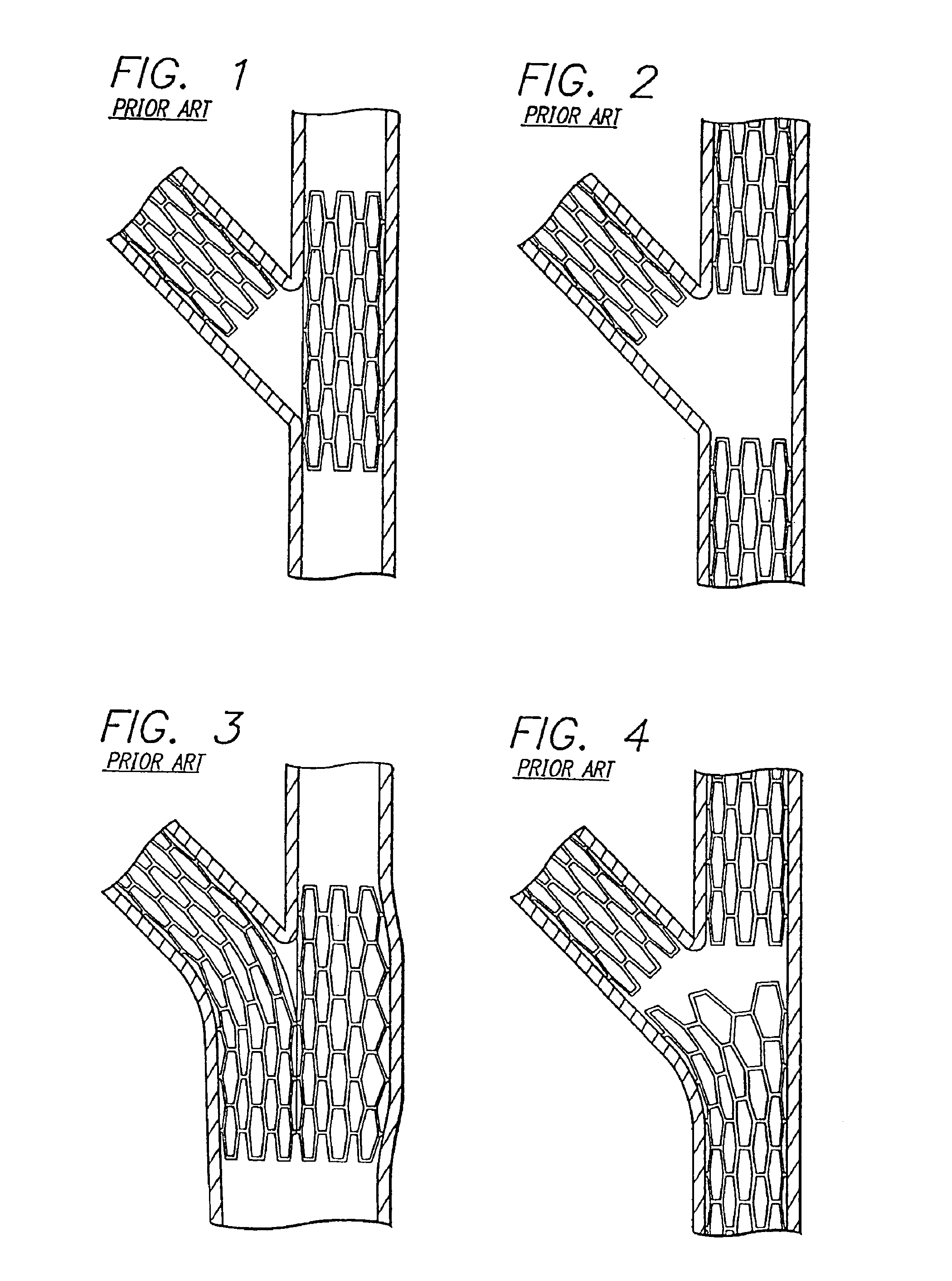
Where the stent does not overlay the entire circumference of the ostium to the diseased portion, the stent fails to completely repair the bifurcated vessel.
Where the stent overlays the entire circumference of the ostium to the diseased portion, yet extends into the junction comprising the bifurcation, the diseased area is repaired, but blood flow may be compromised in other portions of the bifurcation.
Unapposed stent elements may promote lumen compromise during neointimalization and healing, producing restenosis and requiring further procedures.
Moreover, by extending into the junction comprising the bifurcation, the stent may block access to portions of the bifurcated vessel that require performance of further interventional procedures.
Similar problems are encountered when vessels are diseased at their angled origin from the aorta as in the ostium of a right coronary or a vein graft.
In this circumstance, a stent overlying the entire circumference of the ostium extends back into the aorta, creating problems, including those for repeat catheter access to the vessel involved in further interventional procedures.
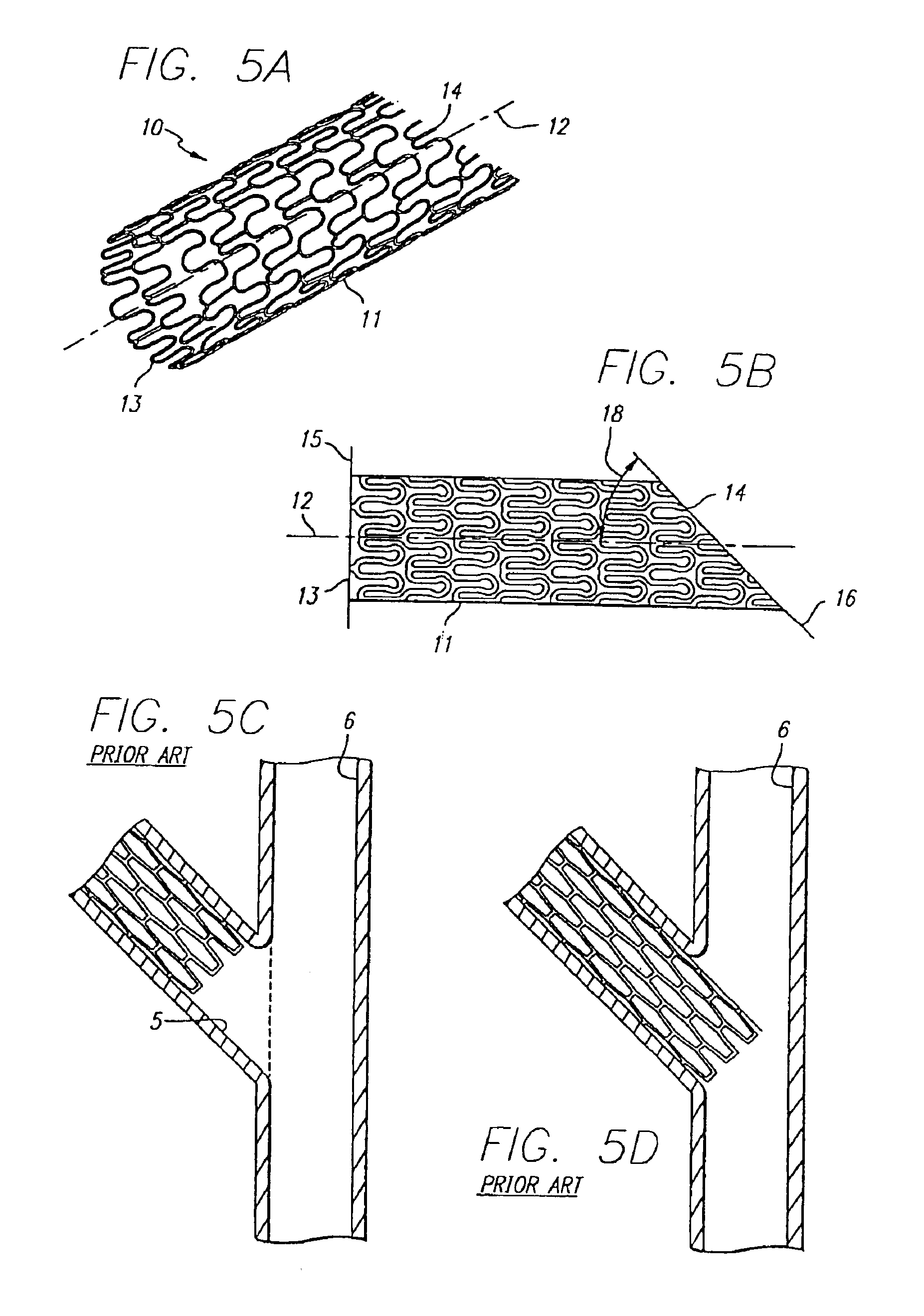
Conventional stents are designed to repair areas of blood vessels that are removed from bifurcations and, since a conventional stent generally terminates at right angles to its longitudinal axis, the use of conventional stents in the region of a vessel bifurcation may result in blocking blood flow of a side branch or fail to repair the bifurcation to the fullest extent necessary.
Such a position of the conventional stent results in a bifurcation that is not completely repaired.
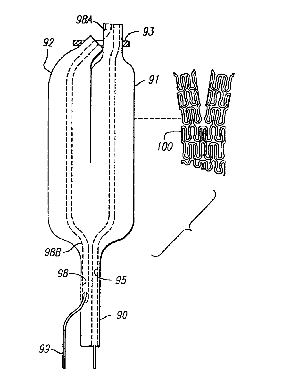
In addition to the problems encountered by using the prior art stents to treat bifurcations, the delivery platform for implanting such stents has presented numerous problems.
The drawback with this approach is there is no way to determine or guarantee that the main-vessel stent struts are properly oriented with respect to the side branch or that the appropriate cell has been selected by the wire for dilatation.
The aperture created often does not provide a clear opening and creates a major distortion in the surrounding stent struts.
The drawback with this approach is that there is no way to tell if the main-vessel stent struts have been properly oriented and spread apart to provide a clear opening for stenting the side-branch vessel.
One of the drawbacks of this approach is that the orientation of the stent elements protruding from the side-branch vessel into the main vessel is completely random.
When dilating the main vessel stretching the stent struts is therefore random, leaving the possibility of restricted access, incomplete lumen dilatation, and major stent-distortion.
All of the foregoing stent deployment assemblies suffer from the same problems and limitations.
An uncovered flap or fold in the intima or plaque will invite a “snowplow” effect, representing a substantial risk for subacute thrombosis, and the increased risk of the development of restenosis.
Further, where portions of the stent are left unapposed within the lumen, the risk for subacute thrombosis or the development of restenosis again is increased.
The prior art stents and delivery assemblies for treating bifurcations are difficult to use, making successful placement nearly impossible.
Further, even where placement has been successful, the side-branch vessel can be “jailed” or covered so that there is impaired access to the stented area for subsequent intervention.
In addition to problems encountered in treating disease involving bifurcations for vessel origins, difficulty is also encountered in treating disease confined to a vessel segment but extending very close to a distal branch point or bifurcation which is not diseased and does not require treatment.
In such circumstances, very precise placement of a stent covering the distal segment, but not extending into the ostium of the distal side-branch, may be difficult or impossible.

Method used


Image

  • Stent and catheter assembly and method for treating bifurcations
  • Stent and catheter assembly and method for treating bifurcations
  • Stent and catheter assembly and method for treating bifurcations

Examples


Embodiment Construction

[0086]The present invention includes an assembly and method for treating bifurcations in, for example, the coronary arteries, veins, arteries, and other vessels in the body. Prior art attempts at implanting intravascular stents in a bifurcation have proved less than satisfactory. For example, FIGS. 1-4 depict prior art devices which include multiple stents being implanted in both the main vessel and a side-branch vessel. In FIG. 1, a prior art “T” stent is implanted such that a first stent is implanted in the side branch near the ostium of the bifurcation, and a second stent is implanted in the main vessel, across the side-branch ostium. With this approach, portions of the side-branch vessel are left uncovered, and blood flow to the side-branch vessel must necessarily pass through the main-vessel stent, causing possible obstructions or thrombosis.

[0087]Referring to FIG. 2, three prior art stents are required to stent the bifurcation. In FIG. 3, the prior art method includes implanti...


PUM


Abstract

An apparatus and method is provided for stenting bifurcated vessels. A proximal angled stent is configured for implanting in a side-branch vessel wherein the proximal angled stent has an angulated portion that corresponds to the angle formed by the intersection of the side-branch vessel and the main vessel so that all portions of the side-branch vessel at the bifurcation are covered by the proximal angled stent. A main-vessel stent is provided for implanting in the main vessel, wherein the main-vessel stent has an aperture or stent cell that aligns with the opening to the side-branch vessel to permit unobstructed blood flow between the main vessel and the side-branch vessel. Side-branch and main-vessel catheter assemblies are advanced over a pair of guide wires for delivering, appropriately orienting, and implanting the proximal angled stent and the apertured stent.

Description

[0001]This application is a continuation of, U.S. Ser. No. 10 / 620,942 filed Jul. 16, 2003, which is a continuation U.S. Ser. No. 10 / 353,116 filed Jan. 27, 2003, which is a continuation of U.S. Ser. No. 09 / 882,989 filed Jun. 14, 2001 now U.S. Pat. No. 6,579,312, which is a continuation of U.S. Ser. No. 09 / 412,113 filed Oct. 5, 1999 now U.S. Pat. No. 6,264,682, which is a continuation of U.S. Ser. No. 08 / 910,857 filed Aug. 13, 1997 now U.S. Pat. No. 6,165,195.BACKGROUND OF THE INVENTION[0002]1. Field of the Invention[0003]The invention relates to stent deployment assemblies for use at a bifurcation and, more particularly, a catheter assembly for implanting one or more stents for repairing bifurcations, the aorto-ostium, and bifurcated blood vessels that are diseased, and a method and apparatus for delivery and implantation.[0004]2. Prior Art[0005]Stents conventionally repair blood vessels that are diseased and are generally hollow and cylindrical in shape and have terminal ends that a...

Claims


Application Information

Patent Timeline
Patent Type & Authority Patents(United States)
IPC IPC(8): A61F2/06A61F2/00A61M25/08A61F2/82A61F2/90A61M25/12
CPCA61F2/856A61F2/91A61F2/915A61F2/954A61F2/958A61M25/10A61F2/90A61M2025/1045A61F2002/065A61F2002/067A61F2002/821A61F2002/91508A61F2002/91516A61F2002/91533A61F2002/91575A61F2250/0014A61F2250/006
Inventor WILSON, W. STANMAUCH, KEVIN M.
Owner ABBOTT CARDIOVASCULAR
Why Eureka
Try Eureka