Image forming apparatus and fixing device therefor

a technology of image forming apparatus and fixing device, which is applied in the direction of ohmic-resistance heating, electrographic process apparatus, instruments, etc., can solve the problems of slow heating of the heat roller to the fixing temperature, needing to feed preheating current to the developing device, and long warm-up time of the heat roller. , to achieve the effect of short warm-up time and energy saving

Inactive Publication Date: 2005-05-24
RICOH KK
View PDF20 Cites 7 Cited by
  • Summary
  • Abstract
  • Description
  • Claims
  • Application Information

AI Technical Summary

Benefits of technology

[0021]It is another object of the present invention to provide a fixing device using a halogen heater achieving a short warm-up time and saving energy, and an image forming apparatus including the same.

Problems solved by technology

Such a short warm-up time makes it needless to feed preheating current to the developing device even in a stand-by state.
However, the warm-up time of the heat roller is longer than the warm-up time available with the direct heating system.
The problem with the indirect heating type of fixing device is that the warm-up of the heat roller to the fixing temperature is slow, as stated earlier.
However, this kind of scheme reduces the rigidity of the heat roller and makes it impossible to reduce the thermal capacity beyond a certain limit while maintaining the minimum mechanical strength.
The loss ascribable to the glass tube of the halogen heater is generally considered to be about 5% of the entire radiation and technically unavoidable because of such a low ratio.
However, in the energy saving type of fixing device whose warm-up time to the fixing temperature is as short as about 10 seconds, the warm-up time of the radiation heater itself just after the turn-on of the power source is not negligible.
Another problem with the conventional halogen heater is that its response at the time of turn-on and turn-off is slow and brings about the temperature ripple of the heat roller when a paper sheet arrives at the fixing device.
Rush current that flows when the power source is turned on is still another problem particular to the halogen heater.

Method used


Image

  • Image forming apparatus and fixing device therefor
  • Image forming apparatus and fixing device therefor
  • Image forming apparatus and fixing device therefor

Examples


first embodiment

[0071]To reduce a heat loss ascribable to the glass tube 28 and therefore the warm-up time of the fixing unit 16, the transmission of the glass tube 28 may be increased. The transmission of the glass tube 28 can be increased if the wall thickness of the tube 28 is reduced or if the transparency of the same is increased.

[0072]In the illustrative embodiment the glass tube 28 has a mean transmission of 94% or above with respect to light whose wavelength is 300 nm to 3,000 nm. By increasing the conventional transmission of 80% to 94% or above, it is possible to improve the efficiency of the halogen heater 23 at the time of warm-up and therefore to reduce the heat loss ascribable to the glass tube 28 which absorbs radiation from the tungsten filament 29, to 5% or below. More specifically, the transmission of the glass tube 28 can be increased if the wall thickness of the glass tube 28 is reduced, if the transparency of the same is increased, or if such schemes are effected in combination...

second embodiment

[0093]In an alternative embodiment to be described, the color temperature of the tungsten filament 29 during fixation is selected to be 2,500 K or above. A color temperature is determined by the diameter and length of the tungsten filament 29, the kind of gas confined in the glass tube 28, and input power. A color temperature refers to the temperature of a perfect radiator radiating light of the same color as light radiated from a given radiator. When the rated power and voltage of the halogen heater 23 are determined, resistance is automatically determined, so that the diameter and length of the tungsten filament 29 are adjusted. Resistance is proportional to the length of the tungsten filament 29, but inversely proportional to the cross section of the same. Therefore, if the tungsten filament 29 has a diameter of 80%, a heater having the same resistance can be produced with the length of 64% (=0.8^2) and the thermal capacity (=volume) of 51.2% (=0.8^3). It follows that the diamete...

third embodiment

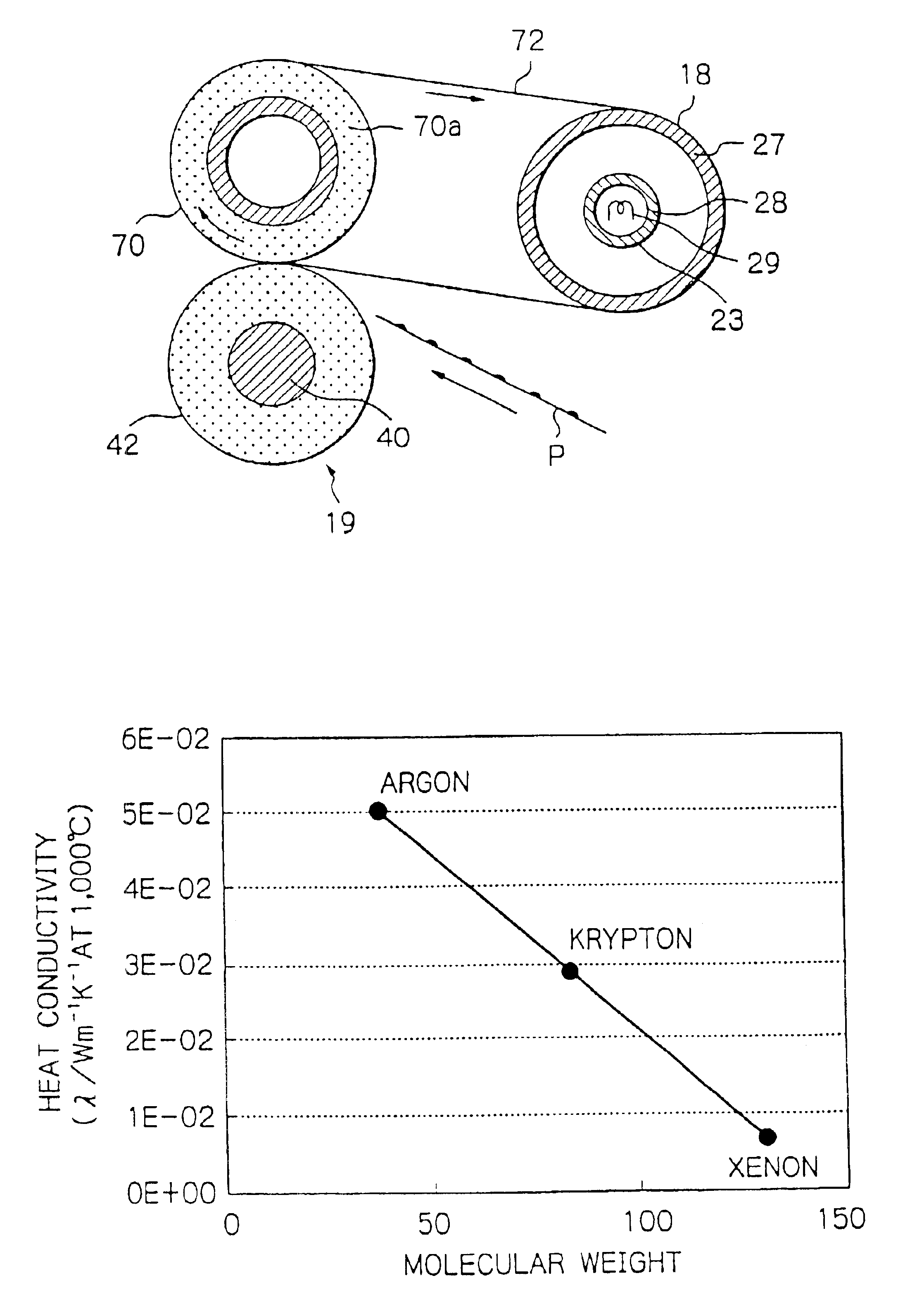
[0120]In another alternative embodiment to be described, the inactive gas is implemented by gas whose major component is krypton. Generally, a glass tube and gas confined therein absorb about one-fourth of radiation from a filament, resulting in a heat loss that slows down warm-up. The illustrative embodiment pays attention to and improves a heat loss relating to heat transfer that is ascribable to the convection of the gas in the glass tube. Specifically, the illustrative embodiment suppresses heat migration in the glass tube 28 due to the inactive gas so as to reduce the heat loss in the glass tube 28 as far as possible.

[0121]FIG. 24 compares argon, krypton and xenon, which are specific inactive gases, with respect to heat conductivity. As shown, krypton is lower in heat conductivity than argon, but higher in heat conductivity than xenon. Stated another way, krypton is higher in molecular weight than argon, but smaller in molecular weight than xenon. While nitrogen or argon has cu...


PUM


Abstract

A fixing device for forming a toner image formed on a recording medium includes a heat roller accommodating a halogen heater. The halogen heater includes a glass tube formed of transparent quartz and provided with a wall thickness of 0.8 mm or below to increase transmission thereof. The increased transmission reduces a heat loss ascribable to the glass tube at the time of warm-up of the fixing device. The heat roller has such a thermal capacity that it can be warmed up in 10 seconds or less. The glass tube is filled with inactive gas whose major component is krypton or xenon. A tungsten filament accommodated in the glass tube has its diameter reduced in order to implement a color temperature of 2,500 K or above. An image forming apparatus using the fixing device is also disclosed.

Description

CROSS-REFERENCED TO RELATED APPLICATION[0001]The present application is a continuation of U.S. application Ser. No. 10 / 132,522 filed Apr. 26, 2002 now U.S. Pat. No. 6,646,227, the entire contents of which are hereby incorporated herein by reference.BACKGROUND OF THE INVENTION[0002]The present invention relates to a copier, printer, facsimile apparatus or similar image forming apparatus and more particularly to a fixing device included in an image forming apparatus for fixing a toner image on a recording medium by using a halogen heater as a heat source.[0003]A copier, for example, electrostatically forms a latent image representative of a document image on a photoconductive element or image carrier, develops the latent image with developing means to thereby produce a corresponding toner image, and transfers the toner image to a paper sheet or similar recording medium. The copier then fixes the toner image on the paper sheet with a fixing device including a heat roller. The fixing de...

Claims


Application Information

Patent Timeline
Patent Type & Authority Patents(United States)
IPC IPC(8): G03G15/20
CPCG03G15/2053
Inventor YURA, JUNFUJITA, TAKASHIIKENOUE, HIROKAZUNAKAFUJI, ATSUSHI
Owner RICOH KK
Why Eureka
Try Eureka