System for transmitting the position of a control element

a control element and transmitting position technology, applied in the field of sensing systems, can solve the problems of insufficient precise or permanent availability of transmitted position signals, excessive consumption of rest current for continuous service,

Inactive Publication Date: 2005-05-24
CONTINENTAL TEVES AG & CO OHG
View PDF11 Cites 2 Cited by
  • Summary
  • Abstract
  • Description
  • Claims
  • Application Information

AI Technical Summary

Benefits of technology

[0009]The system of the present invention includes two or more channels to enhance the reliability of operation. The system is designed with three channels in a particularly favorable manner. To render the channels largely independent, suitably, also the voltage supply means associated with the channels are configured independently. Reliability is considerably enhanced by a redundant design of important system functions.
[0011]In a preferred aspect, at least one signal channel has a lower position resolution than the other signal channel(s). The channel with the lower position resolution may this way be operated permanently with low power consumption.
[0028]A pulse for the signal-conditioning circuit is favorably produced when the position of the control element has changed by the width of a zone of the encoder. The result is a smaller pulse distance at an increasing rate of motion of the control element.
[0036]Preferably, pulses counted incorrectly in the recalibration device are eliminated with each zero point transition (full relief of the brake pedal). This is possible because the control element, usually in the non-actuated condition, returns into a more or less precisely defined initial position. This rules out a negative position.

Problems solved by technology

These systems suffer, among others, from the shortcoming that they are especially susceptible to disturbances.
Further, the transmitted position signals are not sufficiently precise or permanently available, respectively, due to the hysteresis and wear of the potentiometer contacts.
Still further, active systems for travel measurement are known apart from the above-described passive systems, the said active systems being considerably more sophisticated in terms of circuit technology and, consequently, exhibiting a rest current consumption which is too high for continuous service.

Method used


Image

  • System for transmitting the position of a control element
  • System for transmitting the position of a control element
  • System for transmitting the position of a control element

Examples


Embodiment Construction

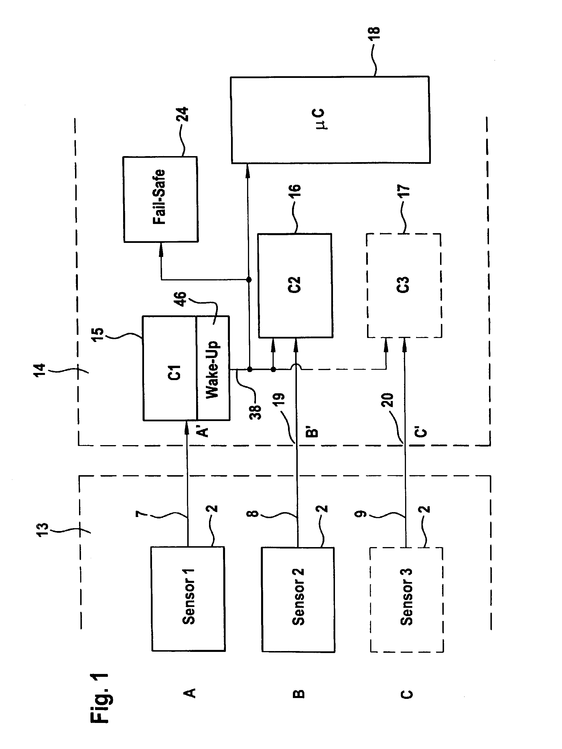
[0047]The basic function blocks of the system according to the present invention are described by way of FIG. 1.

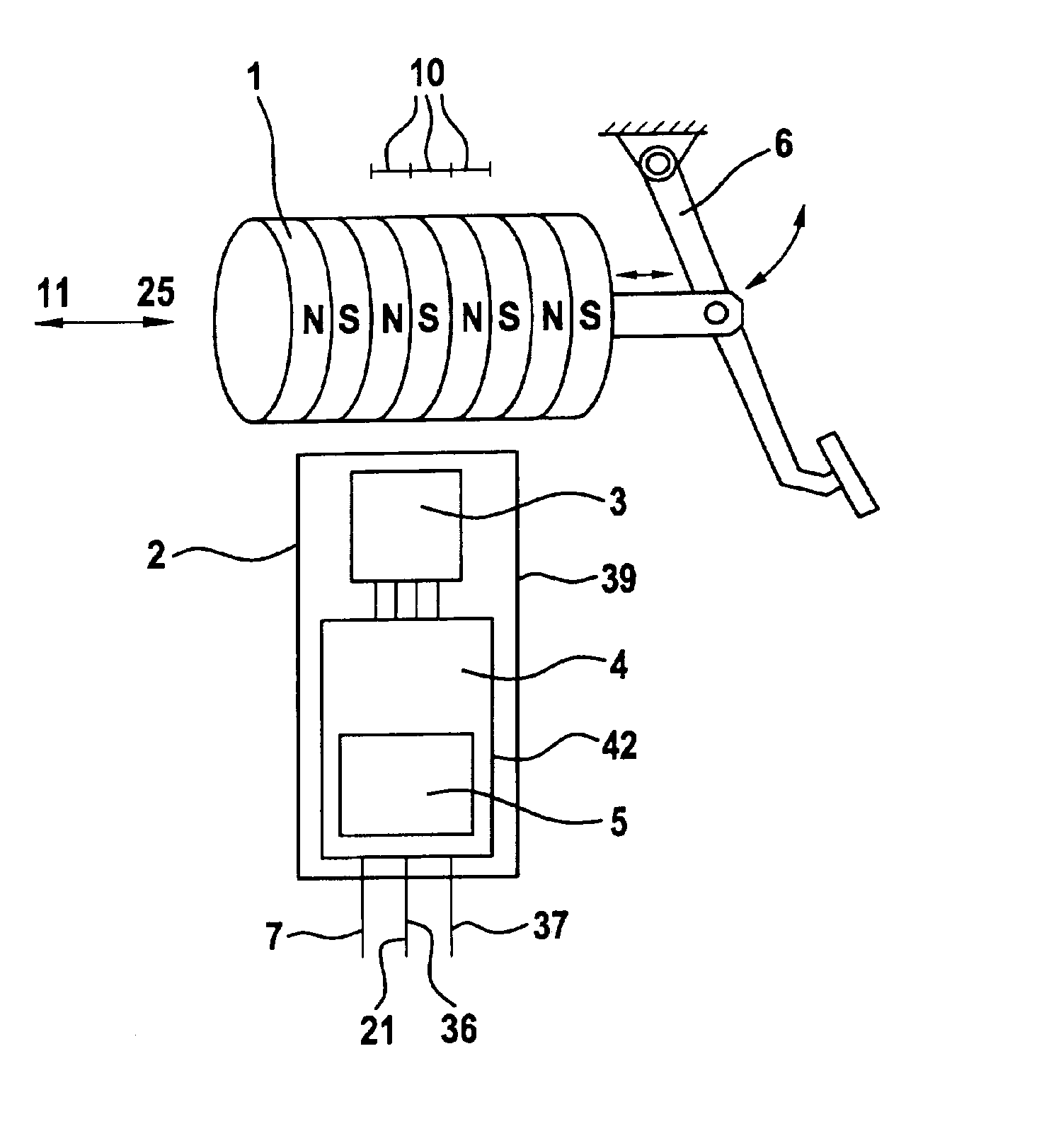
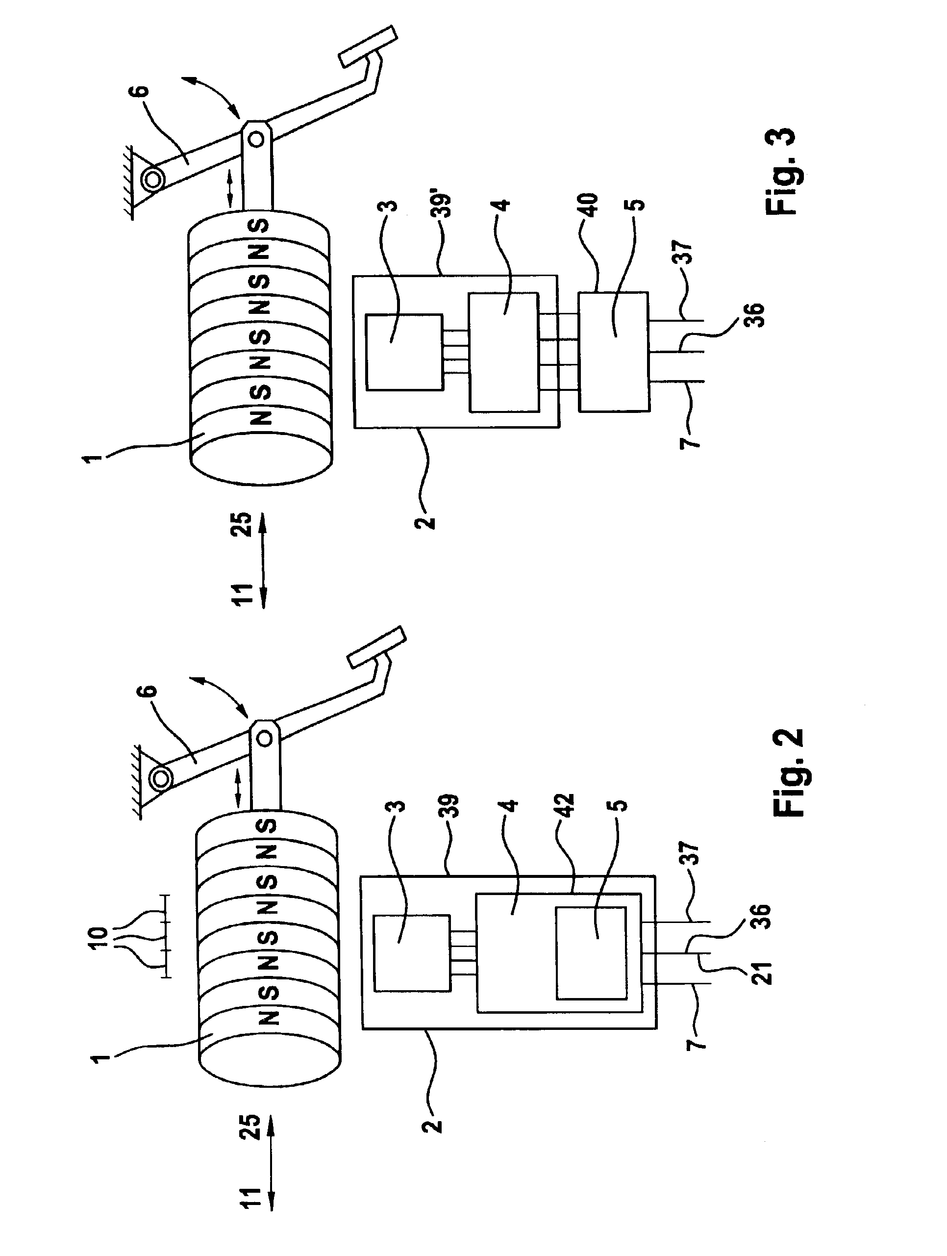
[0048]As many as three signal channels A, B, C (which are basically completely independent of one another and have one signal line 7, 8, 9 each) are employed to transmit the position signals from the position transmitters for brake pedal sensors illustrated in FIGS. 3 and 4. Channel A′ in the receiving circuit 14 which is associated with sensor channel A is designed for the operation with a comparatively low power consumption and is in permanent operation. In the sleep condition the other channels are deactivated, meaning that their voltage supply is disabled. When a valid signal for wake-up is detected in channel A′, the wake-up device 46 will activate the other channels B′ and C′ by way of line 38, as well as the microcomputer 18 and a monitoring circuit (fail-safe logic) which executes defined error-monitoring measures such as monitoring the counts of the position count...


PUM


Abstract

The present invention relates to a system for reliably transmitting the position of a control element to an electronic processing unit by way of electric signal lines, wherein the position signal is transmitted by way of several signal channels, and use thereof in a motor vehicle brake system. The present invention further describes a position transmitter for transmitting position signals with a magnetic encoder which is displaceable by a control element in relation to a magnetic transformer, wherein the magnetic transformer(s) along with an integrated electronic signal-conditioning circuit are arranged in an electronic sensor subassembly, as well as a receiving device for receiving a position signal comprising several processing channels for processing the position signals of the position transmitter.

Description

TECHNICAL FIELD[0001]The present invention generally relates to sensing systems and more particularly relates to a system for reliably transmitting the position of a control element to an electronic processing unit.BACKGROUND OF THE INVENTION[0002]In the majority of cases, modern motor vehicles are equipped with brake systems in which the brake pedal pressure is transmitted to the brake cylinders—mostly boosted by a brake booster—by way of hydraulic lines. In motor vehicles of the next generation, the motion signal of the brake signal generator, upon the driver's request for braking, will not be transmitted exclusively hydraulically to a (hydraulic or electric) brake control device but by means of electric lines (these systems are commonly known as brake-by-wire systems). In addition to an electric signal transmission in the electro-hydraulic brake (EHB), a hydraulic line may be provided in addition to the electric line between the brake pedal and the brake control device for an eme...

Claims


Application Information

Patent Timeline
Patent Type & Authority Patents(United States)
IPC IPC(8): B60T7/04B60T17/18B60T8/17
CPCB60T7/042B60T17/18B60T2220/04B60T15/54
Inventor LOHBERG, PETERFEY, WOLFGANGENGELMANN, MARIORINK, KLAUSBECKMANN, TOBIAS
Owner CONTINENTAL TEVES AG & CO OHG
Why Eureka
Try Eureka