Signboard device

Inactive Publication Date: 2005-05-31
HYNYANG FRAME CO LTD
View PDF18 Cites 19 Cited by
  • Summary
  • Abstract
  • Description
  • Claims
  • Application Information

AI Technical Summary

Benefits of technology

[0024]According to another aspect of the present invention, the base, the post, the post cover unit and the signboard frame are made of a lightweight aluminum material having good corrosion resistance.
[0025]According to the present invention, the signboard unit can be easily installed on the post, and has excellent structural strength enough to resist flexure and deformation due to external force. A plurality of signboard units can be simply installed in all directions on a single post.
[0026]Since the signboard unit is provided therein with sufficient space, it is possible to provide remarkable visual effectiveness under poor viewing conditions when illumination equipment is provided in the space. Even when

Problems solved by technology

Furthermore, since the hinge brackets of the signboard must be connected to the lugs of the cantilever hanger by hinge bolts and hinge nuts, respectively, an operation of coupling the signboard to the post is considerably complicated.
In this case, the installation operation of the signboards is considerably complicated, production cost is increased and scenery is significantly spoiled.
Furthermore, although the respective components, manufactured from an iron material, are then coated with paint, the components are apt to be oxidized and corroded due to paint damage at their coupled portions after an extended period of time, thereby causing contamination of the post and reduction of its service life, if not in fact frequent change of the post.
However, the above conventional signboard devices have disadvantages in that since the signboard must be manufactured using a thin plate, due to the fact that the signboard must be fitted into a narrow gap between the two fork plates of the holder and then held thereto, the signboard is inevitably weak in its structural strength and thus apt to be bent or deformed by c

Method used


Image

  • Signboard device
  • Signboard device
  • Signboard device

Examples


Embodiment Construction

[0040]This invention will be described in further detail by way of example with reference to the accompanying drawings.

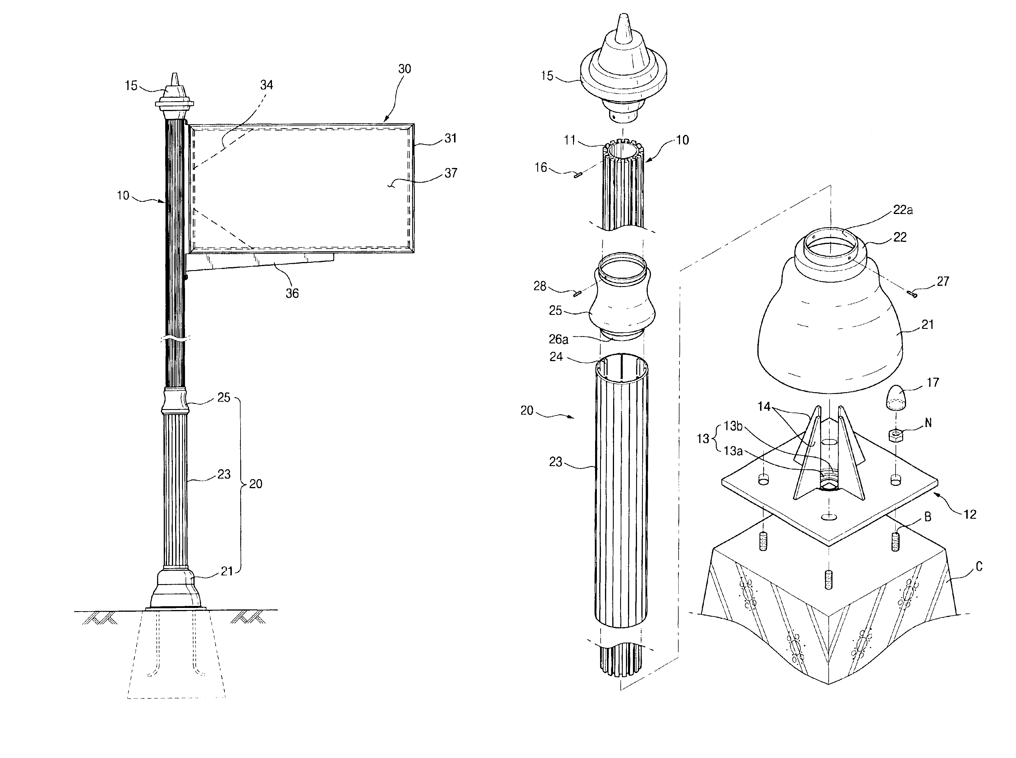
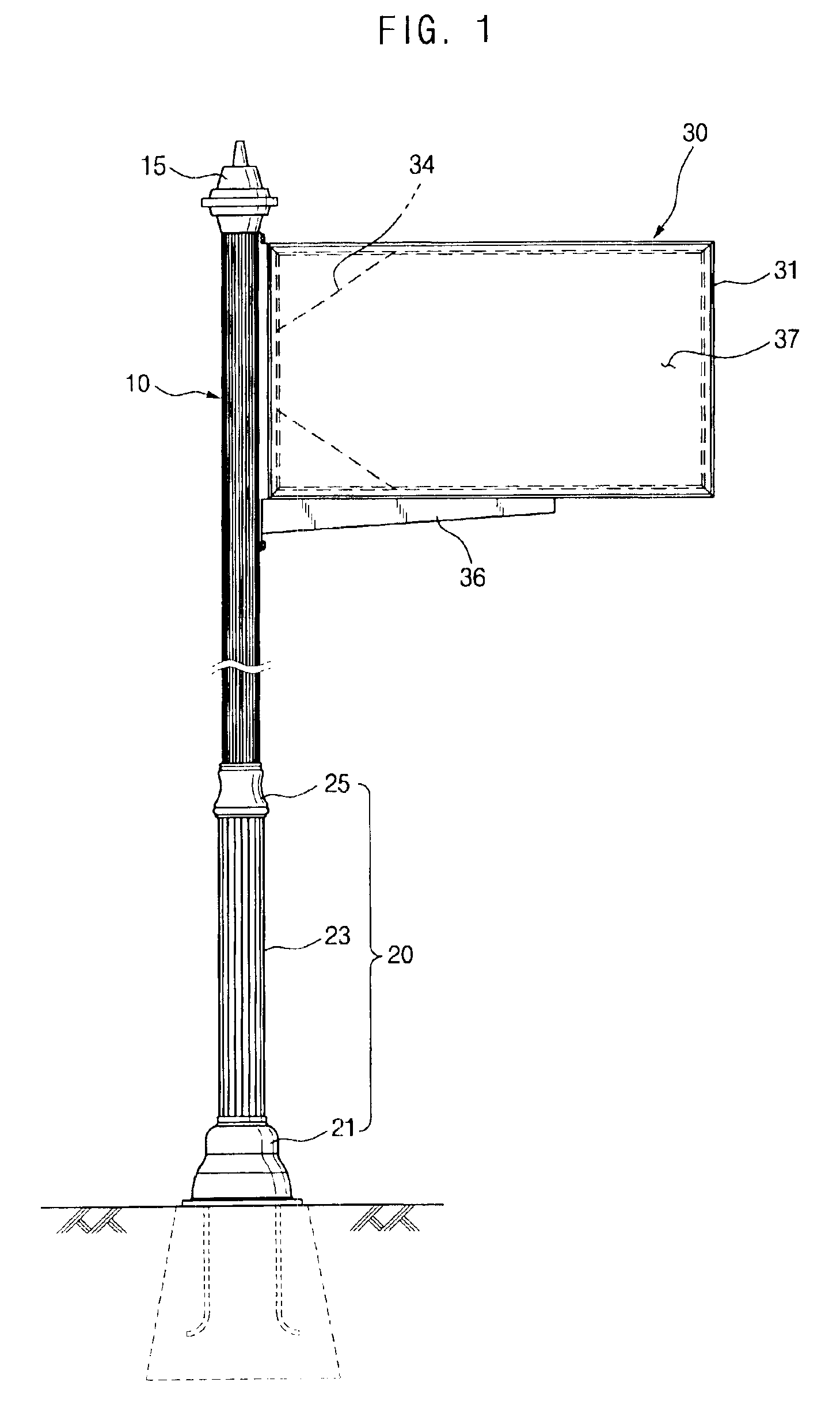
[0041]Referring to FIGS. 1 to 6 of the drawings, there is shown a signboard device according to the present invention. As shown in FIGS. 1 to 6, the signboard device comprises a post 10 vertically installed on a roadside, a post cover unit 20 surrounding a lower portion of the post 10 to protect the portion from external impact, and a signboard unit 30 joined to an upper portion of the post in a cantilever manner to show desired information.

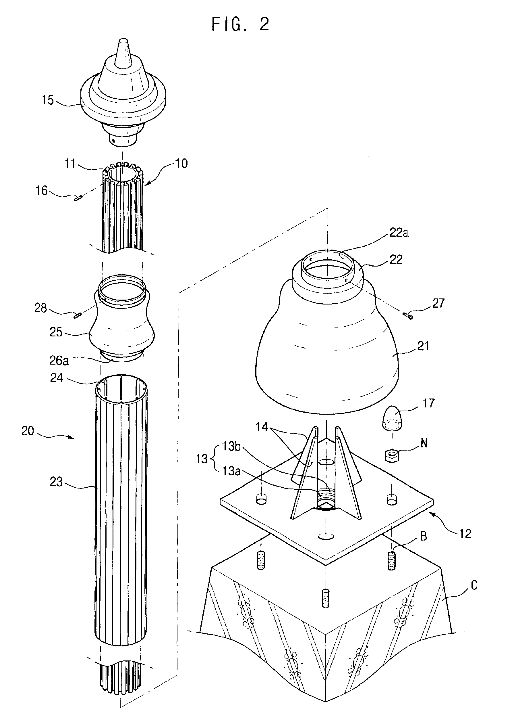
[0042]The post 10 is comprised of a pipe, for example, a pipe of circular section, and is provided at its outer circumferential surface with a plurality of dovetail-shaped fitting grooves 11 at a uniform interval. The post 10 is produced by extruding nonferrous metal having excellent corrosion resistance, preferably aluminum.

[0043]The post 10 is integrally provided at its lower end with a base-plate 12. Accordingly, the post can ...


PUM


Abstract

A signboard device exhibiting information regarding roads, buildings or street names is disclosed. The device includes a post having a plurality of fitting grooves at its outer surface; a base joined to a concrete foundation, the base having a post-seating stepped recesses comprised of two concentric recesses; a post cover unit comprised a lower cover, a cylindrical intermediate cover and an upper cover; a signboard unit comprised of a signboard frame assembly and a pair of signboards attached to the stepped lines of the signboard frame assembly; and a stopper for fixing the signboard frame assembly to the post. The device enables one or more signboards to be easily installed on a post, and has excellent structural strength and an adaptable appearance.

Description

BACKGROUND OF THE INVENTION[0001]1. Field of the Invention[0002]The present invention relates to a signboard device installed on a roadside to exhibit information regarding roads, buildings, or street names for convenience of drivers or pedestrians, and more particularly to a signboard device which allows a signboard showing driving or walking information to be easily and stably attached to a post and which provides an acceptable appearance of the signboard and the post in order to improve the cityscape.[0003]2. Description of the Prior Art[0004]In general, various road signs, which are intended to show drivers and pedestrians information relating to dangerous circumstances of a road to assure safety and smooth driving conditions, and which are further intended to provide drivers and pedestrians with information relating to a road, such as direction of a road, distance to a destination, and notable destination points, are installed on roadsides for drivers' and pedestrians' convenie...

Claims


Application Information

Patent Timeline
IPC IPC(8): G09F15/00G09F7/18E01F9/615E01F9/623E01F9/658E01F9/685E01F9/696E04H12/08
CPCG09F15/0037G09F7/18E04H12/08
Inventor KIM, YONG SOO
Owner HYNYANG FRAME CO LTD
Why Eureka
Try Eureka