Electronic endoscope system for reducing random noise of a video signal

a video signal and endoscope technology, applied in the field of electronic endoscope systems, can solve the problems of straining the eyes of observers, affecting the displayed image, and light amount may appear as noise, and achieve the effect of effectively reducing random nois

Inactive Publication Date: 2005-05-31
HOYA CORP
View PDF5 Cites 125 Cited by
  • Summary
  • Abstract
  • Description
  • Claims
  • Application Information

AI Technical Summary

Benefits of technology

[0005]It is therefore an object of the invention to provide an improved electronic endoscope system in which random noise is effectively reduced.

Problems solved by technology

Such a variation of the light amount may appear as noise and affect the displayed image.
Further, other noise such as that due to dark current or the like may also affect the displayed image.
If an observation is completed within a relatively short period noise may not be a large problem, however, if the observation continues for a relatively long period, noise may cause strain on the observer's eyes and an accurate diagnosis may not be made.

Method used


Image

  • Electronic endoscope system for reducing random noise of a video signal
  • Electronic endoscope system for reducing random noise of a video signal
  • Electronic endoscope system for reducing random noise of a video signal

Examples


first embodiment

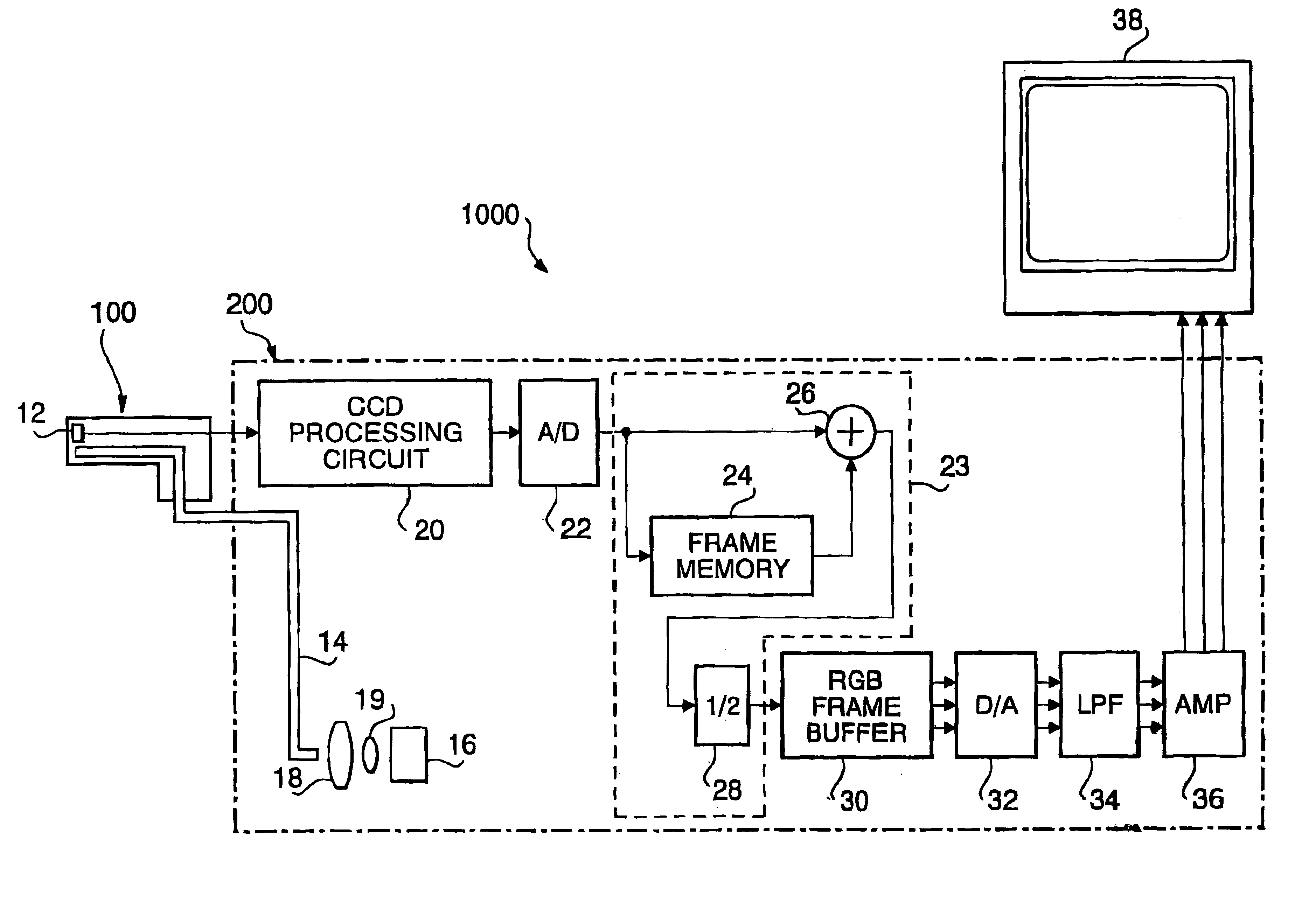
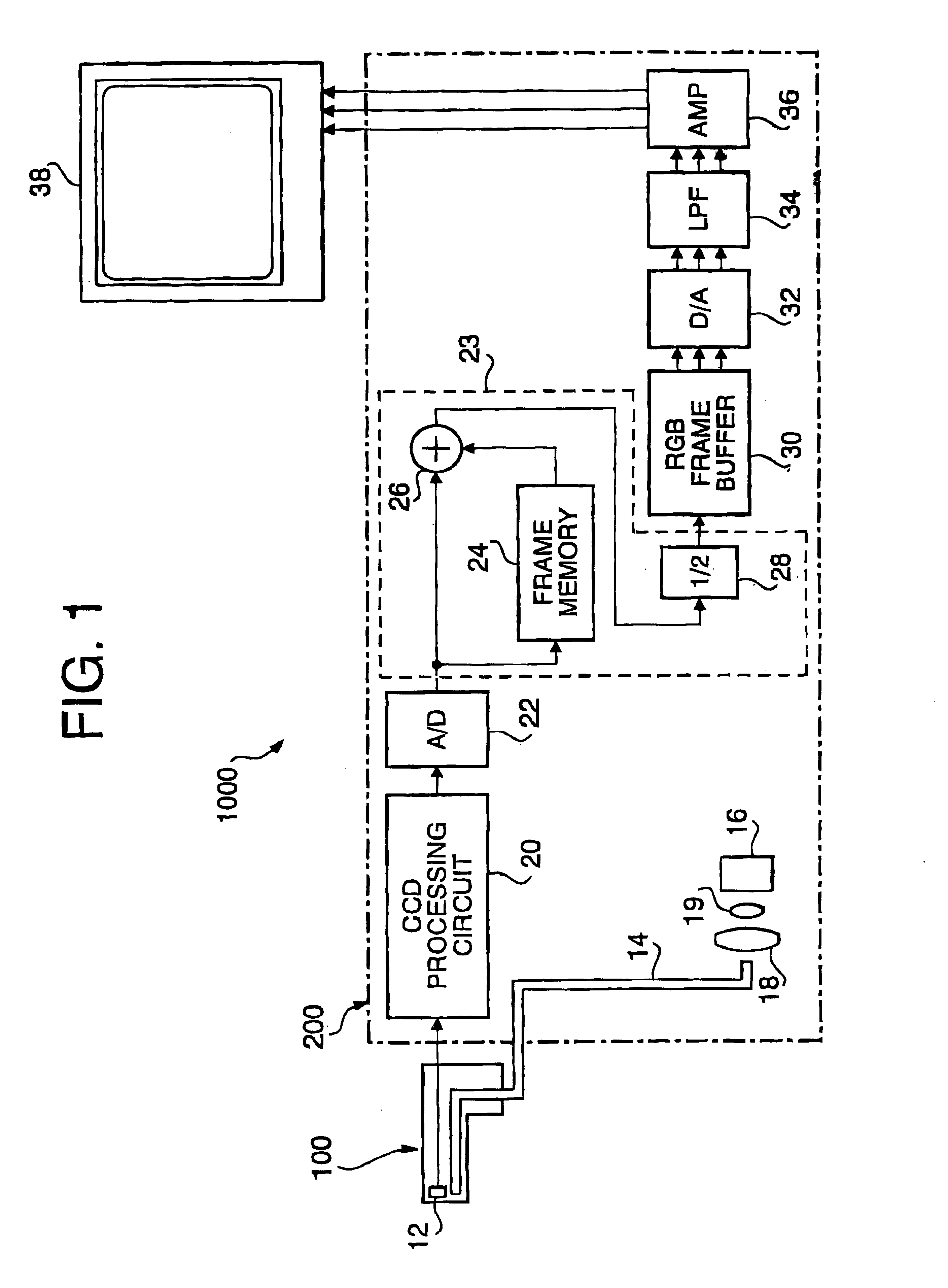
[0042]FIG. 1 is a block diagram of an endoscope system 1000 according to the invention. The endoscope system 1000 includes an endoscope unit 100, a light source unit 200 and a display 38. The endoscope unit 100 has, for example, a flexible tube accommodating a CCD 12 and an objective optical system (not shown) at a distal end of the endoscope unit 100. An image of an object is formed on the light receiving surface of the CCD 12 by the optical system. A light guide 14, such as an optical fiber bundle, runs from the light source unit 200 and then from a proximal (operator side) end of the endoscope unit 100 to the distal end of the endoscope unit 1000. In the light source unit 200, a proximal (operator-side) end of the light guide 14 faces a light source 16 through a converging lens 19 and a color filter disk 18. The light source emits a white light which includes light having various wavelengths, including red, green and blue components. The light emitted by the light source 16 is co...

second embodiment

[0058]FIG. 5 is similar to FIG. 3 and shows the related signals in accordance with the

[0059]A current digital image signal is multiplied by α and a previous noise-reduced digital image signal from the frame memory is multiplied by (1−α). The current digital image signal and the previous digital image signal are then added to obtain a resultant noise-reduced digital image signal in which random noise is reduced. The noise-reduced digital image signal is also stored in the frame memory 44 for use in subsequent image signal processing as a previous noise-reduced digital image signal.

[0060]Similarly to the first embodiment, the noise-reduced digital image signal is output from the adder 42 to the RGB frame buffer 30 and processed accordingly for display on the display 38.

[0061]According to the second embodiment, the noise-reduced digital image signal, which has been processed to reduce random noise, is fedback and used as a previous noise-reduced digital image signal such that there wil...

third embodiment

[0063]FIG. 6 is a block diagram showing a noise reduction system 23b according to a

[0064]In this embodiment, the previous noise-reduced digital image signal is read out of the frame memory 44 and applied to both the adder 42 and a sign-reversing amplifier 48. The sign of the previous noise-reduced digital image signal is reversed by the sing reversing amplifier 48 and the sign reversed signal is applied to a second adder 50. The second adder 50 also receives the current digital image signal from the A / D converter 22. Therefore, the output of the second adder 50 represents the difference between the current digital image signal and the previous noise-reduced digital image signal for each color. The output of the second adder 50 is multiplied by the coefficient α in the first multiplier 40 and input to the adder 42. The adder 42 adds the previous noise-reduced digital image signal from the frame memory 44 and the output of the first multiplier 40 to produce a resultant noise-reduced d...


PUM


Abstract

An electronic endoscope system which captures an image of an object and displays the same on a display device is provided with a noise reduction system. The noise reduction system reduces noise included in a frame of an image signal for each color component. The noise-reduced color components are stored in a buffer, and then output as a video signal to be transmitted to a display where a color image of the object is displayed.

Description

BACKGROUND OF THE INVENTION[0001]The present invention relates to an electronic endoscope system to be used for displaying a color image of an object.[0002]Generally, an electronic endoscope system is provided with an endoscope having a flexible tube accommodating an image sensor (such as a CCD) (Charge Coupled Device) and an objective lens at a distal end thereof. An image of an object is formed on an image receiving surface of the CCD by the objective lens system. The flexible tube also accommodates an optical fiber bundle. The distal end of the optical fiber bundle is located at the distal end of the flexible tube, and the proximal (operator-side) end of the optical fiber bundle is coupled to a light source unit to face to a light source included in the light source unit. Accordingly, light emitted by the light source is transmitted through the optical fiber bundle and illuminates the object.[0003]The CCD includes a plurality of pixels. However, since the number of pixels for the...

Claims


Application Information

Patent Timeline
Patent Type & Authority Patents(United States)
IPC IPC(8): A61B1/04G02B23/24H04N7/18
CPCA61B1/045G06T5/002G06T5/50H04N9/646G06T2207/10068G06T2207/30004G06T2207/10016
Inventor OZAWA, RYOIKETANI, KOUHEI
Owner HOYA CORP
Why Eureka
Try Eureka