Package structure for a hybrid optical module and method of producing the same

a hybrid optical module and packaging technology, applied in the direction of semiconductor laser arrangement, optical head manufacture, semiconductor lasers, etc., can solve the problems of inferior mechanical strength and heat radiation properties of metals, adverse effects on the die-bonding state of another laser device, and inability to meet the requirements of conventional optical pickups configured by discrete components, etc., to achieve the effect of improving the mechanical strength of the resin package, increasing the heat capacity of the heat sink, and increasing the surface area of the fram

Inactive Publication Date: 2005-05-31
PIONEER CORP
View PDF4 Cites 0 Cited by
  • Summary
  • Abstract
  • Description
  • Claims
  • Application Information

AI Technical Summary

Benefits of technology

[0008]The invention has been conducted in view of the above-discussed circumstances. It is an object of the invention to provide a package structure for a hybrid optical module in which components of a hybrid optical module are mounted on a lead frame made of a metal, and the frame is bent in a resin, thereby enhancing the mechanical strength of a resin package, and the surface area of the frame is increased so that the heat capacity in terms of a heat sink is increased, and also a method of producing such a package structure.
[0009]It is another object of the invention to provide a package structure for a hybrid optical module in which, when a plurality of laser devices are to be bonded to a metal frame, the metal frame is independently disposed for each of the laser devices, so that, during a process of die-bonding one laser device, the die bonding of another laser device is not adversely affected and misalignment of the optical axis due to heat applied in the process of die-bonding can be suppressed, and also a method of producing such a package structure.
[0013]When a pickup component is to be die-bonded onto a metal frame, a heat treatment is conducted. In the above configuration, since the metal frame is disposed independently from a metal frame onto which a laser device is to be die-bonded, one laser device is not adversely affected by a process of die-bonding another laser device. Therefore, misalignment of the optical axis due to heat applied in the process of die-bonding can be suppressed. Since the metal frame is bent in the resin package, the strength of the resin package itself is enhanced. Furthermore, the surface area of the metal frame is increased, and hence the heat capacity in terms of a heat sink is increased. Since heat is radiated to the outside via the thin resin package or the frame led-out portion, the heat radiation effect is improved.
[0015]As described above, the other portion of the metal frame is vertically bent in accordance with the shape of the resin package, the other portion of the metal frame is then embedded into the resin package, and a shaping process is performed. The components of the hybrid optical module are mounted on a lead frame made of a metal, and the frame is bent in a resin, so that the mechanical strength of the resin package can be enhanced. The surface area of the frame is increased, whereby the heat capacity in terms of a heat sink can be increased.

Problems solved by technology

However, a conventional optical pickup which is configured by discrete components cannot meet such requests.
The latter material is light in weight and suitable for miniaturization, but is inferior in mechanical strength and heat radiation property than a metal.
During a process of die-bonding one laser device, therefore, the die-bonding state of another laser device may be adversely affected.
In this case, misalignment of the optical axis is caused by heat applied in the process of die-bonding.

Method used


Image

  • Package structure for a hybrid optical module and method of producing the same
  • Package structure for a hybrid optical module and method of producing the same
  • Package structure for a hybrid optical module and method of producing the same

Examples


Embodiment Construction

[0019]Now, a description will be given in more detail of preferred embodiments of the invention with reference to the accompanying drawings.

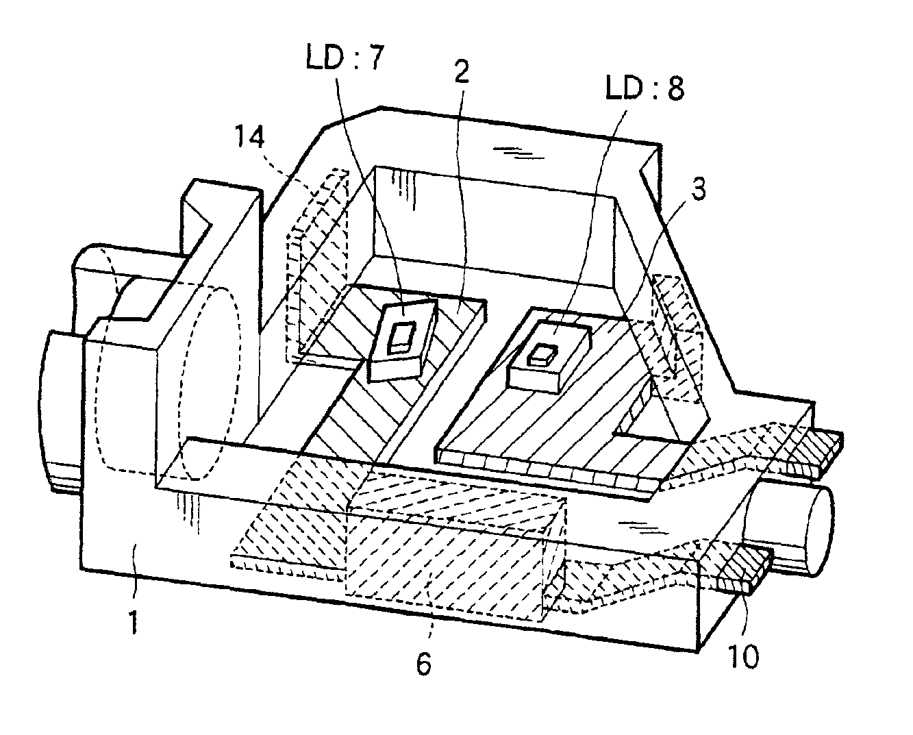
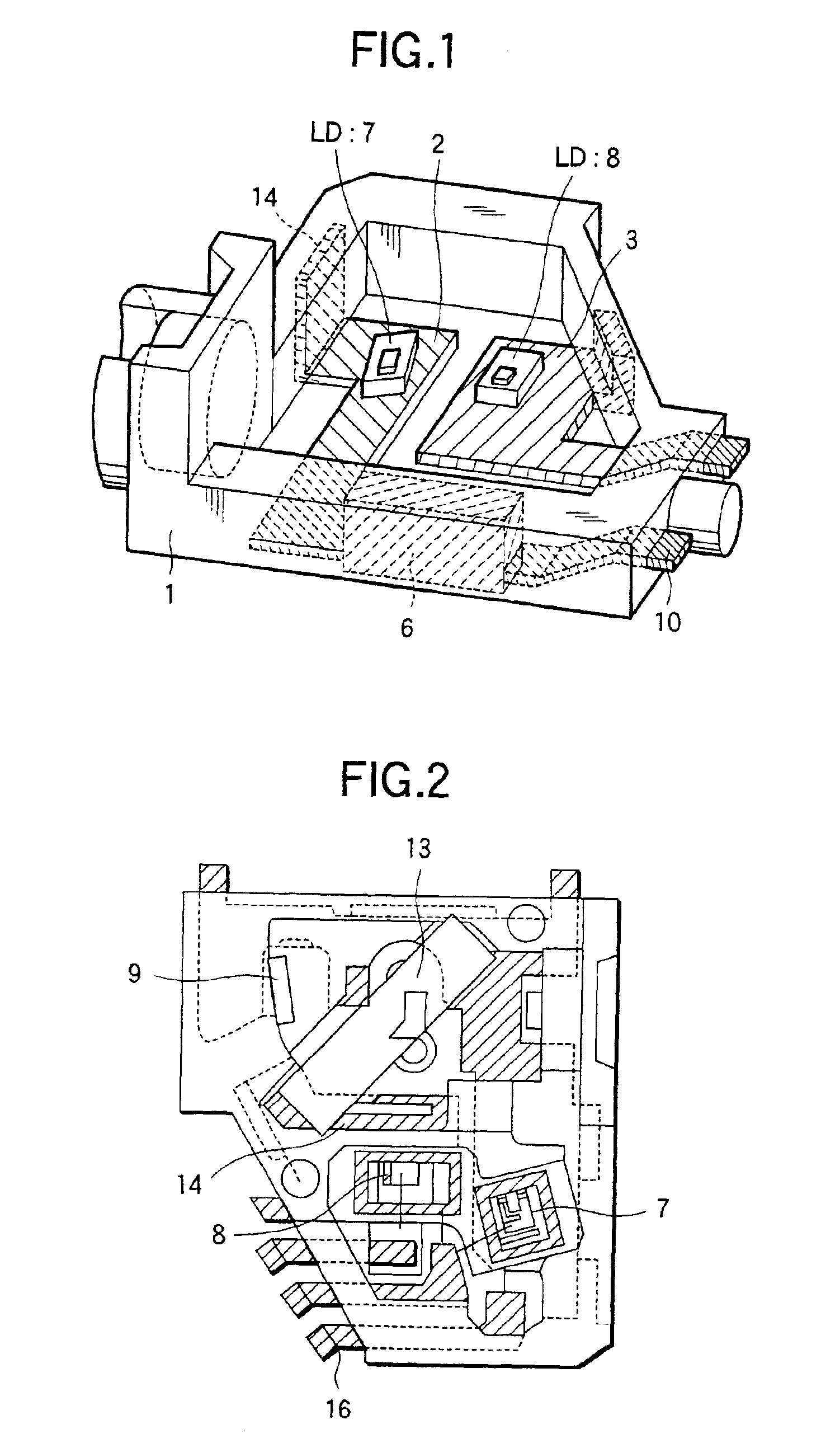
[0020]FIG. 1 is a view showing an embodiment of the package structure for a hybrid optical module according to the invention.

[0021]Referring to the figure, 1 denotes a resin package which is hollowed in order to house components of a hybrid optical module. The reference numeral 2 denotes a lead frame for die-bonding a laser device (LD 7), and 3 denotes a lead frame for die-bonding a laser device (LD 8). Ends of the lead frames are bent, and then embedded into the resin package 1 as in-resin bent portions 4, 5, and 6.

[0022]The reference numeral 10 denotes a frame led-out portion through which portions of the lead frames 2 and 3 are led out to the outside of the resin package 1. The led-out portion 10 is made in contact with a metal plate, an aluminum die cast member, or the like which is outside the package, whereby the heat radiation effect can ...


PUM

PropertyMeasurementUnit
temperatureaaaaaaaaaa
shapeaaaaaaaaaa
opticalaaaaaaaaaa

Abstract

A resin package 1 is hollowed in order to house components of a hybrid optical module. Laser devices 7 and 8 are die-bonded to metal frames 2 and 3, respectively. Ends of the metal frames are bent, and then embedded into the resin package 1 as in-resin bent portions 4, 5, and 6. In a frame led-out portion 10, portions of the metal frames 2 and 3 are led out to the outside of the resin package 1. The led-out portion 10 is made in contact with a metal plate, an aluminum die cast member, or the like which is outside the package, whereby the heat radiation effect is improved.

Description

BACKGROUND OF THE INVENTION[0001]1. Field of the Invention[0002]The present invention relates to a package structure for a hybrid optical module in which components of an optical pickup, excluding an objective lens are to be mounted, and also a method of producing it.[0003]2. Description of the Related Art[0004]Among devices constituting a CD player, an optical pickup which detects an optical signal is the heart of the CD player. With respect to such an optical pickup, requests for a reduced cost, a high reliability, and a reduced weight have been given. However, a conventional optical pickup which is configured by discrete components cannot meet such requests. Therefore, optical modules of a hybrid configuration which are called a hologram pickup or a laser coupler have begun to be used.[0005]In such hybrid optical modules, particularly in a laser coupler, all parts other than an objective lens are integrated into one component, so as to extremely reduce the size of the module. Spe...

Claims


Application Information

Patent Timeline
Patent Type & Authority Patents(United States)
IPC IPC(8): G11B7/22G11B7/12H01L25/16H01S5/40H01L33/00H01S5/00H01S5/022H01S5/0232
CPCG11B7/12G11B7/22H01L25/167H01L33/62H01S5/02244H01L2924/0002H01S5/4087H01L2924/00H01S5/0231H01S5/0232
Inventor OKAYASU, MASAKIFUKUDA, SHINNOSUKETANAKA, HIROFUMI
Owner PIONEER CORP
Why Eureka
Try Eureka