Ultra wide bandwidth spread-spectrum communications system

a communication system and ultra wide bandwidth technology, applied in the field of radio communication systems, can solve the problems of interference in the communication system, the current spread-spectrum and narrowband system cannot coexist with other narrowband users of the same spectrum, and the interference is impinging on the other users,

Inactive Publication Date: 2005-05-31
NORTH STAR INNOVATIONS
View PDF140 Cites 142 Cited by
  • Summary
  • Abstract
  • Description
  • Claims
  • Application Information

AI Technical Summary

Problems solved by technology

Current spread-spectrum and narrowband systems cannot coexist with other narrow bandwidth users of the same spectrum due to mutual interference.
Too much interference is impinged on the other users, who themselves cause too much interference to the communication system.
Typically, high-speed links operate on microwave carriers that are easily blocked by terrain and intervening objects.
But conventional systems typically have less than 10% bandwidth, and therefore have poor resolution at low frequencies.
Due to this poor duty cycle, it is difficult to impossible to generate significant average power efficiently, or in an integrated circuit, because the peak voltages are higher than breakdown voltage of state-of-the-art low voltage CMOS and Bipolar processes.
Yet another difference is interference.

Method used


Image

  • Ultra wide bandwidth spread-spectrum communications system
  • Ultra wide bandwidth spread-spectrum communications system
  • Ultra wide bandwidth spread-spectrum communications system

Examples


Embodiment Construction

[0081]In the detailed descriptions we describe the operation of the UWB short pulse transmitter and receiver. Both cases begin with expressions for the key waveforms generated, and then relate their elements to the circuits.

Transmitter

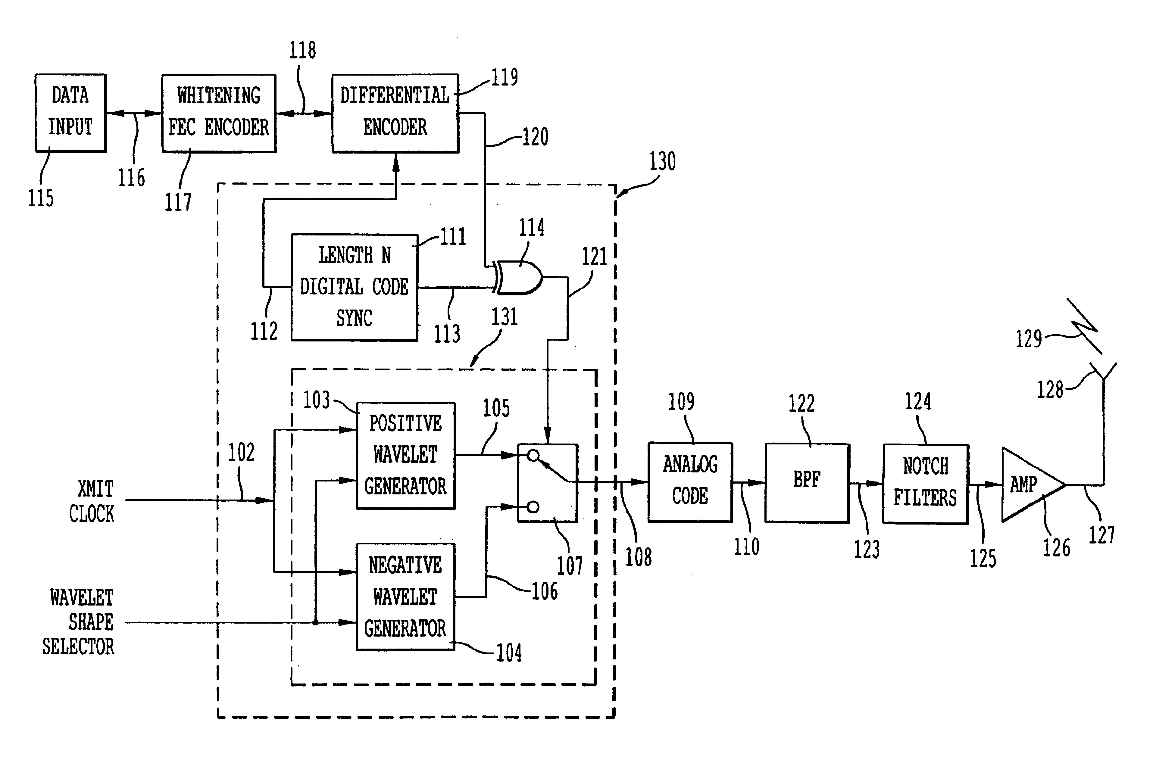
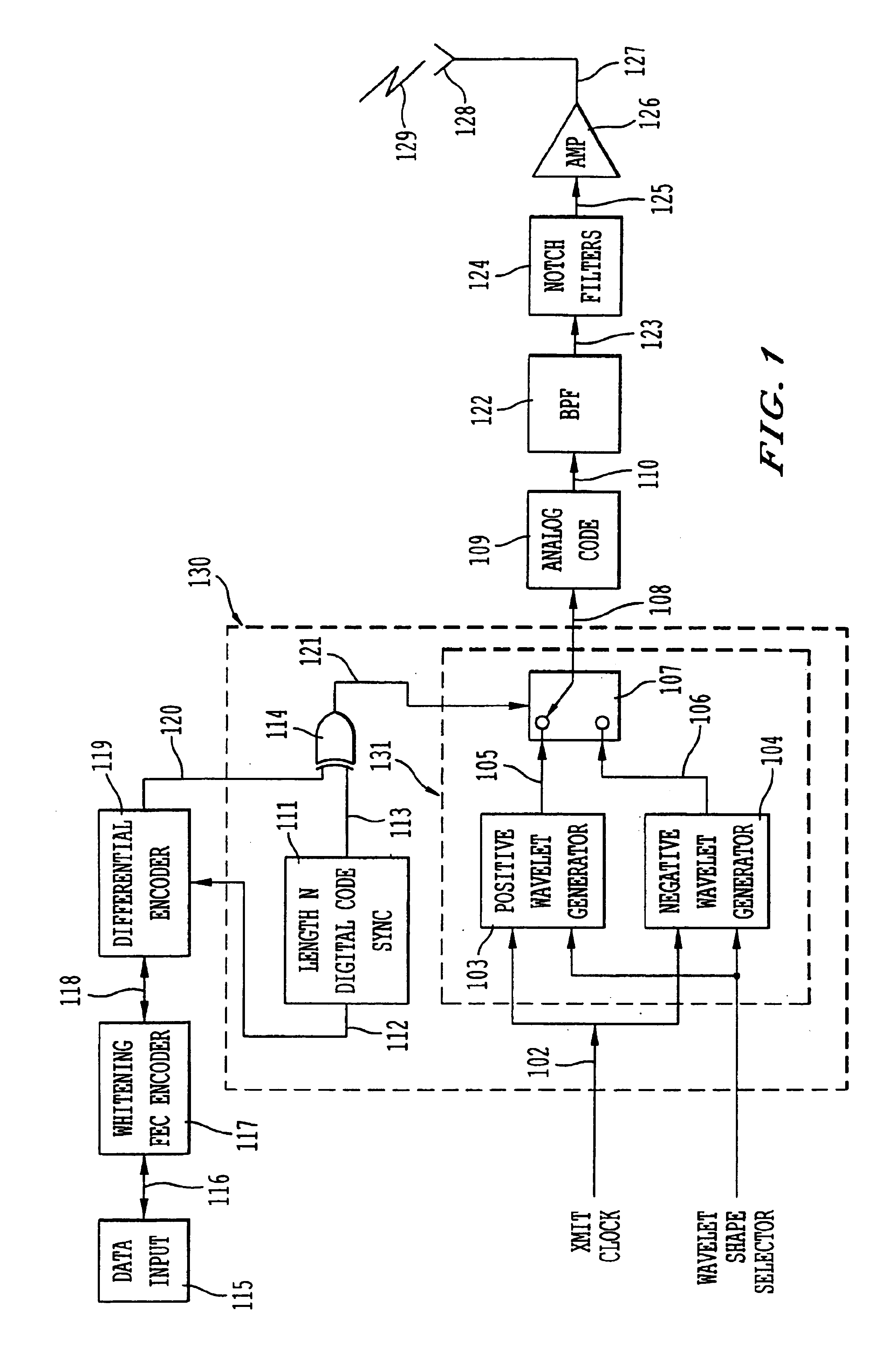
[0082]A block diagram of the transmitter is shown in FIG. 1. Its goal is to generate the waveform of equation (11), which was x⁡(t)=d⁡(t)*h⁡(t)*s⁡(t)=(∑k=0Nd-1⁢ ⁢dk⁢δ⁡(t-kTc))*(∑n=0Nc-1⁢ ⁢hn⁢δ⁡(t-Tn))*s⁡(t).=∑k=0Nd-1⁢∑n=0Nc-1⁢ ⁢dk⁢hn⁢s⁡(t-Tn-kTc)(13)

[0083]In this formulation, the transmit waveform is defined as the convolution of the data stream d(t) with the code h(t), and the underlying pulse s(t).

Data Stream

[0084]The transmitter receives data from data input 115. Mathematically, the binary data d(t) are represented by a stream of equispaced impulses, one per data bit, indexed by k. FIG. 16 is an example for the data dk=[1, 0, 1, 1, 0, 1, 0], as a stream of positive and negative going impulses, one per data bit, where the mapping {0,1}→{−1,1} has bee...


PUM


Abstract

An ultra wide bandwidth, high speed, spread spectrum communications system uses short wavelets of electromagnetic energy to transmit information through objects such as walls or earth. The communication system uses baseband codes formed from time shifted and inverted wavelets to encode data on a RF signal. Typical wavelet pulse durations are on the order of 100 to 1000 picoseconds with a bandwidth of approximately 8 GHz to 1 GHz, respectively. The combination of short duration wavelets and encoding techniques are used to spread the signal energy over an ultra wide frequency band such that the energy is not concentrated in any particular narrow band (e.g. VHF: 30-300 MHz or UHF: 300-1000 MHz) and is not detected by conventional narrow band receivers so it does not interfere with those communication systems. The use of pulse codes composed of time shifted and inverted wavelets gives the system according to the present invention has a spatial resolution on the order of 1 foot which is sufficient to minimize the negative effects of multipath interference and permit time domain rake processing.

Description

CROSS-REFERENCE TO RELATED APPLICATIONS[0001]This application is a continuation of U.S. patent application Ser. No. 09 / 209,460 filed Dec. 11, 1998, now U.S. Pat. No. 6,700,939, which was converted from U.S. provisional application Ser. No. 60 / 069,594 filed Dec. 12, 1997, both of which are hereby incorporated by reference in their entirety.STATEMENT REGARDING GOVERNMENT INTEREST[0002]The Government of the United States of America, as represented by the Secretary of the Army, has certain nonexclusive license rights to the Invention as set forth in rights determination ARL No. 998-679-16.COPYRIGHT NOTICE[0003]Copyright, 1998, XtremeSpectrum, Inc. A portion of the disclosure of this patent document contains material which is subject to copyright protection. The copyright owner has no objection to reproduction by anyone of the patent document or the patent disclosure, as it appears in the U.S. Patent and Trademark Office patent file or records, but otherwise reserves all copyright rights...

Claims


Application Information

Patent Timeline
Patent Type & Authority Patents(United States)
IPC IPC(8): H04B1/69H04L25/49H04L27/00H04B1/7163H04B1/717H04B1/7176H04B1/7183H04B1/719
CPCH04B1/71632H04B1/7174H04L27/0004H04L25/4902H04B1/7176H04B1/7172H04B1/7183H04B1/719
Inventor MCCORKLE, JOHN W.ROFHEART, MARTIN
Owner NORTH STAR INNOVATIONS
Why Eureka
Try Eureka