Apparatus for treating wastes by gasification

a technology of gasification apparatus and waste, which is applied in the direction of combustible gas production, lighting and heating apparatus, furnaces, etc., can solve the problems of incineration, inconvenient recycling of metals discharged from furnaces, and disadvantages of solid waste incineration, and achieve the effect of low cos

Inactive Publication Date: 2005-06-07
EBARA CORP +1
View PDF29 Cites 31 Cited by
  • Summary
  • Abstract
  • Description
  • Claims
  • Application Information

AI Technical Summary

Benefits of technology

[0012]It is therefore an object of the present invention to provide a method and apparatus for treating wastes by gasification which can recover resources of the wastes, open up a road to separation and reuse of the resources, produce synthesis gas having desired components for use for synthesis of ammonia by partial combustion, solve various problems caused by incineration or dumping of organic wastes, and obtain low cost hydrogen (H2) which is used for synthesis of ammonia.

Problems solved by technology

On the other hand, the incineration of solid wastes has been disadvantageous for the following reasons:
However, this incineration has been problematic with respect to environmental conservation, or recycling of resources or energy.
To be more specific, large quantities of exhaust gas are discharged because of high air ratio, and toxic Dioxins are contained in the exhaust gas.
Further, metals which are discharged from the furnace are not suitable for recycling because they are oxidized, and landfill sites become more scarce year by year.
Recently, the number of waste treatment facilities which incorporate ash-melting equipment is increasing, however, a problem is encountered in construction cost and / or operating cost of such waste treatment facilities.
Dumping solid wastes in an untreated state on the land has become more difficult because of scarcity of landfill sites, and has not been allowable from the viewpoint of environmental conservation.
Therefore, there is no site where solid wastes such as shredder dust of scrapped cars can be disposed of.

Method used


Image

  • Apparatus for treating wastes by gasification
  • Apparatus for treating wastes by gasification
  • Apparatus for treating wastes by gasification

Examples


first embodiment

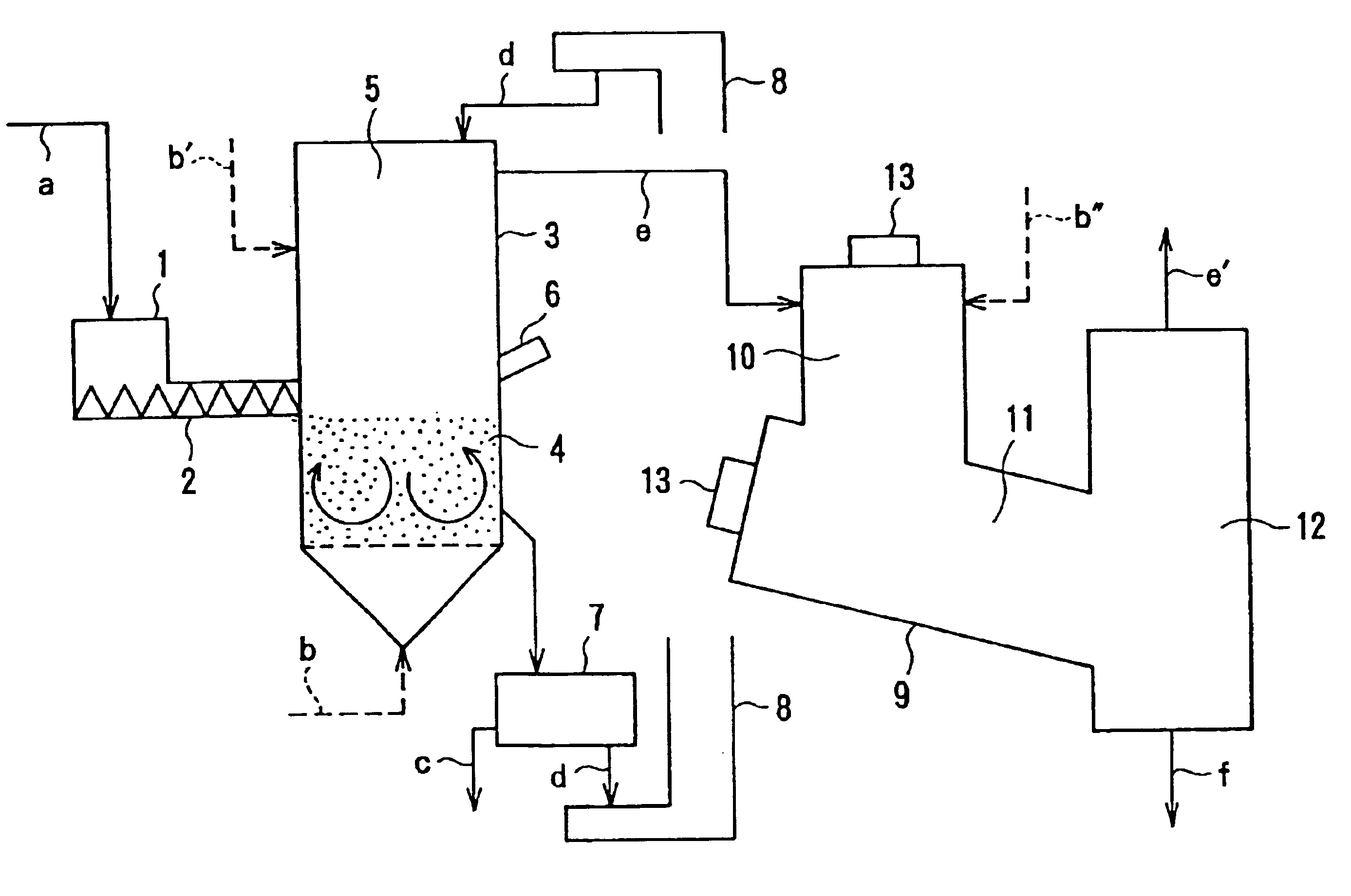
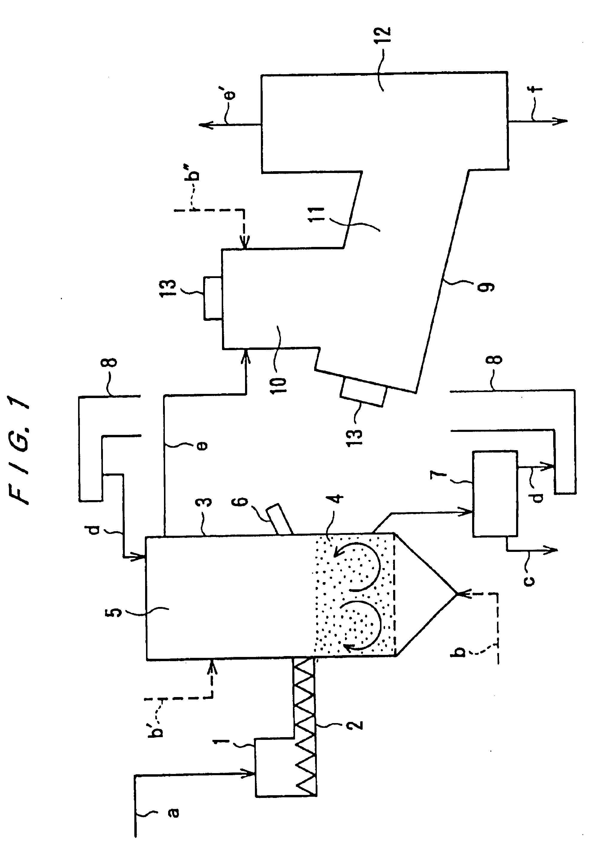
[0068]FIG. 1 schematically shows an apparatus for carrying out the method for treating wastes by gasification according to the present invention.

[0069]The apparatus shown in FIG. 1 includes a hopper 1, a screw feeder 2, and a revolving flow-type fluidized-bed reactor 3 having a fluidized-bed 4 therein. The fluidized-bed reactor 3 has a freeboard 5 and a burner 6, and is connected to a trommel 7 which is associated with a bucket conveyor 8. The apparatus further includes a swirling-type high-temperature combustor 9 having a primary combustion chamber 10, a secondary combustion chamber 11 and a slag separation chamber 12. The swirling-type high-temperature combustor 9 has burners 13. In FIG. 1, the symbols a, b, b′, b″ and c represent organic wastes, air for the fluidized-bed 4, air for the freeboard 5, air for the high-temperature combustor 9, and large-sized incombustibles, respectively. Further, the symbols d, e, e′ and f represent silica sand, generated gas, combustion exhaust gas...

second embodiment

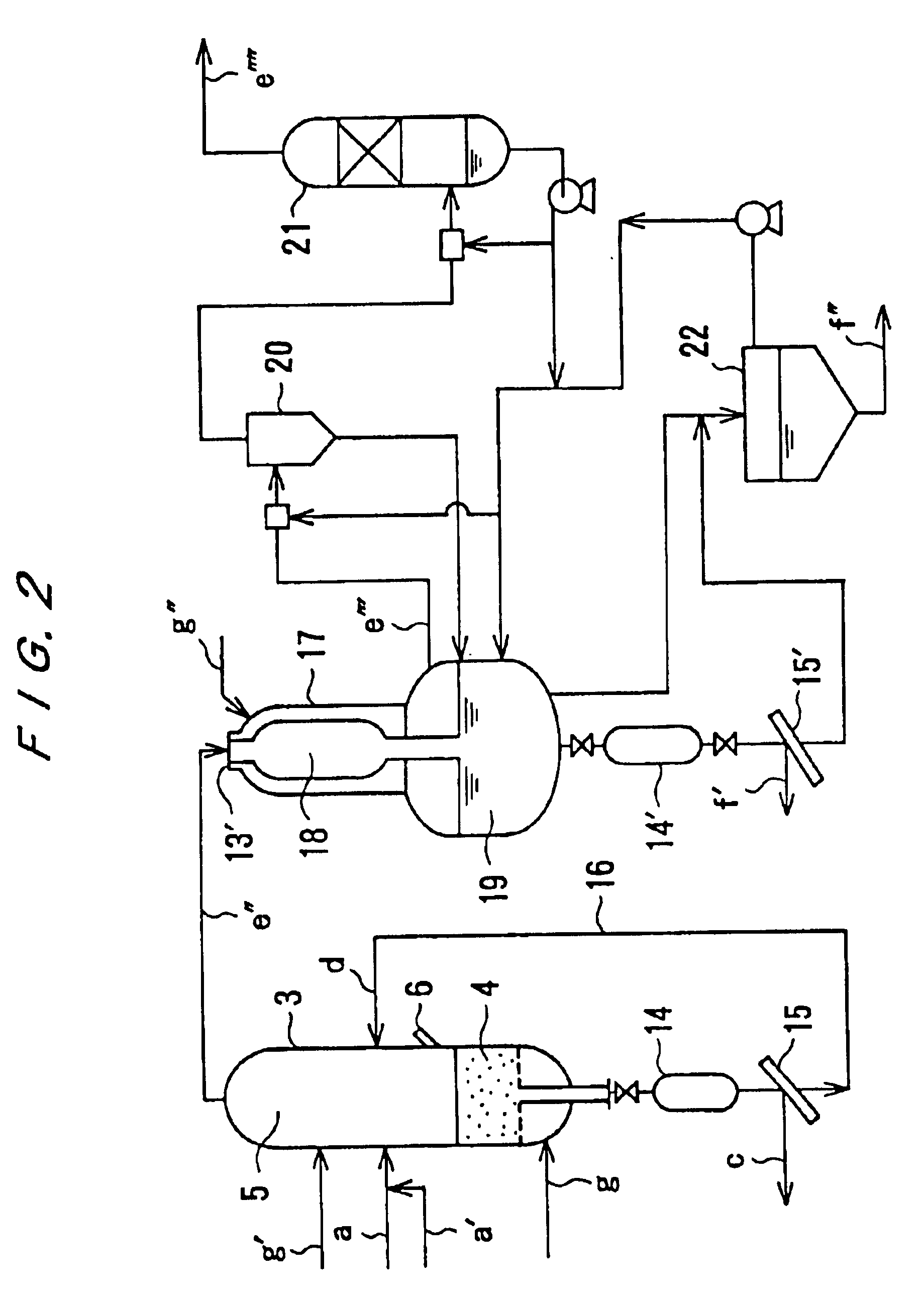
[0075]FIG. 2 shows an apparatus for carrying out the method for treating wastes by gasification according to the present invention.

[0076]The apparatus shown in FIG. 2 serves to produce synthesis. gas having a high pressure ranging from 10 to 40 atm.

[0077]The apparatus comprises a revolving flow-type fluidized-bed reactor 3 and a swirling-type high-temperature combustor 17. The fluidized-bed reactor 3 is connected to a rock hopper 14 which is associated with a screen 15. The swirling-type high-temperature combustor 17 is also connected to a rock hopper 14′ which is associated with a screen 15′. The screen 15 is connected to the fluidized-bed reactor 3 through a fluidized medium circulation line 16. The swirling-type high-temperature combustor 17 has a high-temperature gasification chamber 18 and a quenching chamber 19 therein. The swirling-type high-temperature combustor 17 is connected to a cyclone 20 is connected to a scrubber 21. A settler 22 which is associated with the high-temp...


PUM

PropertyMeasurementUnit
temperatureaaaaaaaaaa
pressureaaaaaaaaaa
pressureaaaaaaaaaa

Abstract

An apparatus for treating wastes includes a fluidized bed reactor for partially combusting the wastes at a relatively low temperature, and a separate relatively high temperature reactor for separate gasification of gaseous material and char from the first gasification. This synthesis gas thus formed is cooled, subjected to a conversion operation in a converter to produce hydrogen.

Description

[0001]The present application is a Division of application Ser. No. 09 / 234,634 filed Jan. 21, 1999, now U.S. Pat. No. 6,063,355, that is a Continuation of application Ser. No. 08 / 757,452 filed Nov. 27, 1996, now U.S. Pat. No. 5,900,224.BACKGROUND OF THE INVENTION[0002]1. Field of the Invention[0003]The present invention relates to a method and apparatus for treating wastes by gasification, and more particularly to a method and apparatus for treating wastes by gasification at a relatively low temperature and then at a relatively high temperature to recover metals or ash content in the wastes in such a state that they can be recycled, and gases containing carbon monoxide (CO) and hydrogen (H2) for use as synthesis gas of ammonia (NH3).[0004]2. Description of the Prior Art[0005]Ammonia (NH3) is a basic material for chemical industries and is mass-produced for use in production of nitric acid, various fertilizers; including ammonium nitrate, ammonium sulfate and urea; acrylonitrile, cap...

Claims


Application Information

Patent Timeline
Patent Type & Authority Patents(United States)
IPC IPC(8): C10J3/46C10J3/00C10J3/56C10J3/54C10J3/66
CPCC10J3/54C10J3/56C10J3/66C10K3/003C10J3/482C10J3/80C10J3/84C10K1/003C10K1/004C10K1/005C10K1/02C10K1/026C10K3/04C10J3/487C10G2300/1003C10J2200/158C10J2300/0946C10J2300/1223C10J2300/1621C10J2300/1668C10J2300/1884
Inventor FUJIMURA, HIROYUKIHIRAYAMA, YOSHIOFUJINAMI, SHOSAKUNAGATO, SHUICHIHIROSE, TETSUHISAOSHITA, TAKAHIROIRIE, MASAAKITAKANO, KAZUOFUKUDA, TOSHIO
Owner EBARA CORP
Why Eureka
Try Eureka