Diamond coated article bonded to a body
a technology of diamond coating and body, applied in the field of new materials, can solve the problem that the coating cannot play any role in supporting fluid
- Summary
- Abstract
- Description
- Claims
- Application Information
AI Technical Summary
Benefits of technology
Problems solved by technology
Method used
Image
Examples
embodiment 1
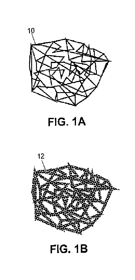
[0030]A first illustrative process for forming a diamond foam article according to the present invention is illustrated in FIG. 3. A silicon carbide foam substrate material 10 (DuoCell / SiC, nominal 25 pores / inch, from ERG Materials and Aerospace Corporation of Oakland, Calif.) having dimensions 1 inch×1 inch×0.25″ thick, is washed for 10 minutes with mild agitation in a solution of isopropyl alcohol containing 10 grams / liter of 0.1 micron diamond dust to induce rapid diamond nucleation and growth in a manner known to the art. The silicon carbide foam is removed from the diamond dust / alcohol slurry and allowed to dry.
[0031]As shown in FIG. 3, the dried silicon carbide foam is then placed in a reactor 20 suitable for diamond deposition using microwave-assisted plasma technology well-known to the art. The foam is supported on quartz supports 22 with one of its broad faces parallel to, and 1 centimeter above, a quartz surface 24, as shown in FIG. 2. The chamber is closed and evacuated. ...
embodiment 2
[0032]A second illustrative process for forming a diamond foam article according to the present invention is illustrated in FIG. 4. A silicon carbide foam substrate material 10 (DuoCell / SiC, nominal 25 pores / inch, from ERG Materials and Aerospace Corporation of Oakland, Calif.) having dimensions 1 inch×1 inch×0.25″ thick, is washed for 10 minutes with mild agitation in a solution of isopropyl alcohol containing 10 grams / liter of 0.1 micron diamond dust to induce rapid diamond nucleation and growth in a manner known to the art. The silicon carbide foam material 10 is removed from the diamond dust / alcohol slurry and allowed to dry.
[0033]The dried silicon carbide foam material 10 is then placed in a reactor 30 suitable for diamond deposition using electrical torch plasma-assisted technology well-known to the art. The deposition chamber 30 is evacuated, and process gases in a mixture of 97 parts hydrogen to 3 parts methane by volume are admitted to the chamber 30. The silicon carbide fo...
embodiment 3
[0035]A third illustrative process for forming a diamond foam article according to the present invention is illustrated in FIG. 5. A silicon carbide foam material 10 is prepared as in the foregoing embodiments. The silicon carbide foam material 10 is placed in a chamber 40 suitable for diamond deposition using the hot filament technology well-known to the art. The silicon carbide foam material 10 is mounted between two arrays 42 of tantalum filaments such that each broad face lies approximately 1 centimeter from its opposed filament array 42 and parallel thereto, as shown in FIG. 4. The deposition chamber 40 is exhausted, and a deposition gas mixture consisting of 98.5 parts hydrogen and 1.5 parts methane by volume is admitted to the chamber 40. Electrical power is applied to the filament arrays 42, heating them to a temperature of 2,100 degrees Centigrade. Pressure in chamber 40 is adjusted to 30 Torr. The silicon carbide foam material 10 is found to exhibit a temperature of approx...
PUM
| Property | Measurement | Unit |
|---|---|---|
| void size distribution | aaaaa | aaaaa |
| thickness | aaaaa | aaaaa |
| thick | aaaaa | aaaaa |
Abstract
Description
Claims
Application Information
 - R&D
- Intellectual Property
- Life Sciences
- Materials
- Tech Scout
- Unparalleled Data Quality
- Higher Quality Content
- 60% Fewer Hallucinations
Browse by: Latest US Patents, China's latest patents, Technical Efficacy Thesaurus, Application Domain, Technology Topic, Popular Technical Reports.
© 2025 PatSnap. All rights reserved.Legal|Privacy policy|Modern Slavery Act Transparency Statement|Sitemap|About US| Contact US: help@patsnap.com


