
Dual wavelength method of determining a relative position of a substrate and a template

a technology of substrate and relative position, applied in the direction of photomechanical equipment, instruments, printers, etc., can solve the problems of prior techniques, high temperature variation, and the inability to use them as a practical substitu

Inactive Publication Date: 2005-06-07
BOARD OF RGT THE UNIV OF TEXAS SYST
View PDF125 Cites 47 Cited by
  • Summary
  • Abstract
  • Description
  • Claims
  • Application Information

AI Technical Summary

Benefits of technology

"The present invention is a method for determining the position of a substrate and a template that are separated. The substrate has alignment marks and the template has corresponding alignment marks. The method involves shining two different lights onto the substrate and template alignment marks. The first light creates a first response, while the second light creates a second response that is different from the first. By processing these responses, a focused image is created that shows the alignment marks on both the substrate and the template. This focused image indicates the relative position of the substrate and the template."

Problems solved by technology

However, most of them have limitations that preclude them from use as a practical substitute for photolithography.
The limitations of these prior techniques include, for example, high temperature variations, the need for high pressures and the usage of flexible templates.
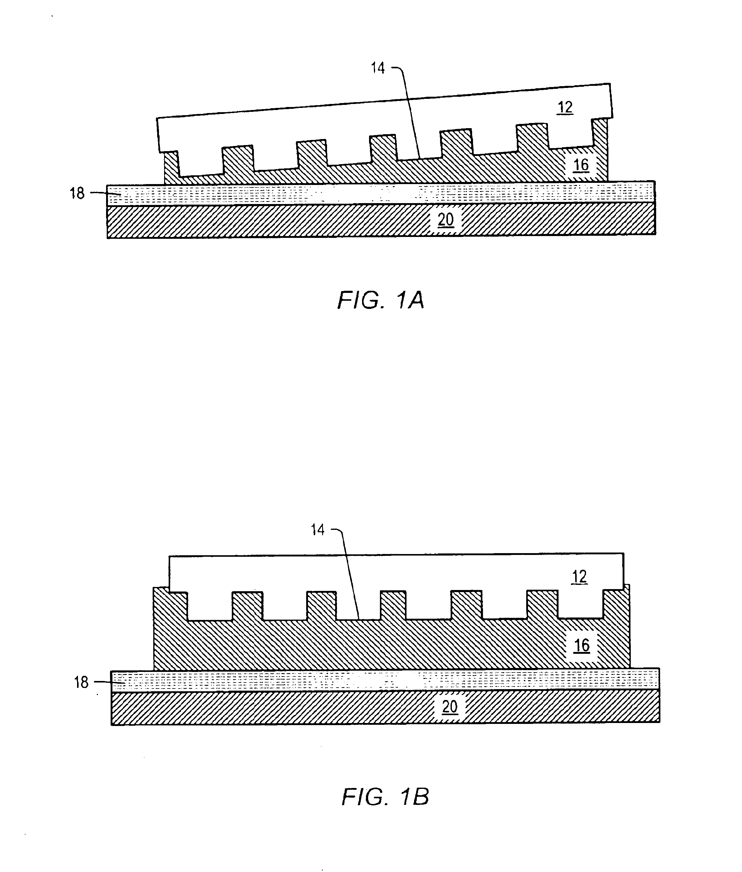
Such distortions can make overlay alignment very difficult to implement.
Overlay errors that typically need to be compensated for include placement errors, theta error and magnification error.
However, these techniques may not be directly applicable to the imprint lithography processes.

Method used


Image

  • Dual wavelength method of determining a relative position of a substrate and a template
  • Dual wavelength method of determining a relative position of a substrate and a template
  • Dual wavelength method of determining a relative position of a substrate and a template

Examples


second embodiment

[0108]an X-Y translation stage is depicted in FIG. 17, and generally referenced by numeral 1700. To provide a similar range of motion to that of X-Y stage 1600, stage 1700 may have a foot print of about 29 inches by 29 inches and a height of about 15 inches (including a wafer chuck). Stages 1600 and 1700 differ mainly in that additional linkages 1701 are oriented vertically, thereby providing additional load bearing support for the translation stage.

[0109]Both X-Y stage 1600 and X-Y stage 1700 are flexure based systems. Flexures are widely used in precision machines since they may offer frictionless, particle-free and low maintenance operation. Flexures may also provide extremely high resolution. However, most flexure based systems may possess limited ranges of motion (e.g., sub mm range of motion). Embodiments disclosed herein may have a range of motion of more than 12 inches. It is believed that such stages may be cost-effective for lithographic applications, particularly in vacuu...

third embodiment

[0143]In a third embodiment, overlay marks may be formed of a different material than the template. For example, a material selected to form the template overlay marks may be substantially opaque to visible light, but transparent to activating light used as the curing agent (e.g., UV light). For example, SiOx where x is less than 2 may form such a material. In particular, it is believed that structures formed of SiOx where x is about 1.5 may be substantially opaque to visible light, but transparent to UV light.

[0144]FIG. 32, depicts an assembly of a system, denoted generally as 100, for calibrating and orienting a template, such as template 12, about a substrate to be imprinted, such as substrate 20. System 100 may be utilized in a machine, such as a stepper, for mass fabrication of devices in a production environment using imprint lithography processes as described herein. As shown, system 100 may be mounted to a top frame 110 which may provide support for a housing 120. Housing 12...

case 1

[0158]Embodiments presented herein may enable measuring a gap or film thickness even when the oscillation of the reflectivity data includes less than one full period within the measuring wavenumber range. In such a case, FFT may result in an inaccurate peak location. In order to overcome such a problem and to extend the lower limit of the measurable film thickness, a novel method is disclosed herein. Instead of using a FFT algorithm to compute the period of the oscillation, an algorithm to find a local minimum (W1) or maximum point (W2) of the reflectivity between Ws and Wf may be used to compute the period information: dR / dw=0 at W1 and W2. The reflectivity R(w) of Equation 7 has its maximum at w=O. Further, the wavenumber range (Δw) of typical spectrometers may be larger than Ws. For a spectrometer with 200 nm-800 nm wavelength range, Δw=3 / 800 whereas Ws=1 / 800. Therefore, the oscillation length of the reflectivity data between 0−Ws may be smaller than that of Δw. As depicted in FI...


PUM

PropertyMeasurementUnit
sizeaaaaaaaaaa
aspect ratioaaaaaaaaaa
surface free energiesaaaaaaaaaa

Abstract

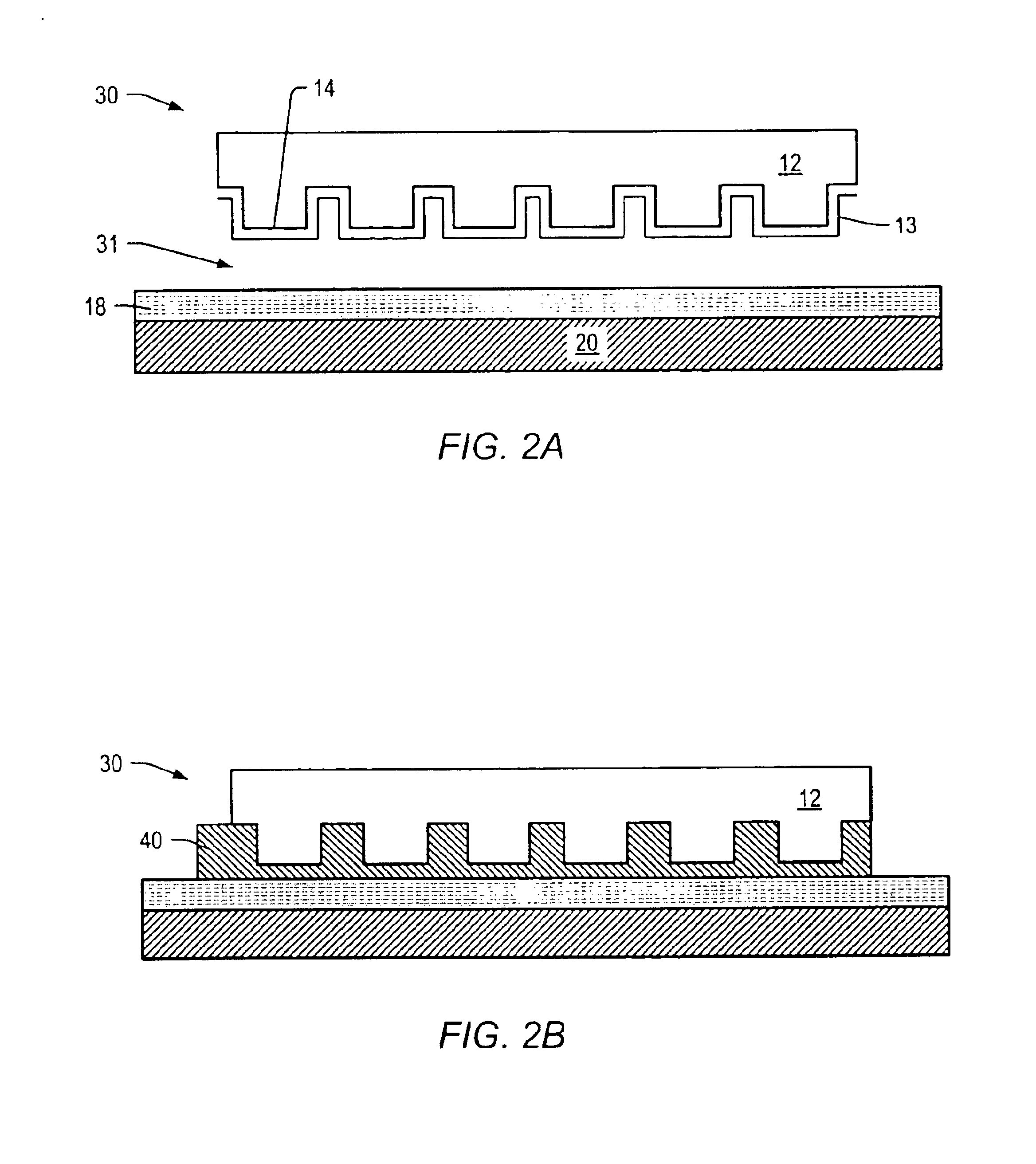
The present invention includes a method of determining a relative position of a substrate and a template spaced-apart therefrom, the substrate having substrate alignment marks disposed thereon and the template having template alignment marks disposed thereon, the method including, impinging first and second fluxes of light upon the substrate and template alignment marks, with the substrate and template alignment marks being responsive to the first flux of light defining a first response, and being responsive to the second flux of light defining a second response differing from the first response; and processing the first and second responses to form a focused image of the substrate and template alignment marks on a common plane, with the focused image indicating the relative position of the substrate and the template.

Description

CROSS-REFERENCE TO RELATED APPLICATIONS[0001]The present application is a divisional of U.S. patent application Ser. No. 09 / 907,512 filed on Jul. 16, 2001 entitled “High Resolution Overlay Alignment Methods and Systems for Imprint Lithography,” which claims priority to U.S. Provisional Patent Application No. 60 / 218,568 filed on Jul. 16, 2000 entitled “High-Resolution Overlay Alignment Methods and Systems for Imprint Lithography,” both of which are incorporated by reference herein.STATEMENT REGARDING FEDERALLY SPONSORED RESEARCH OR DEVELOPMENT[0002]The U.S. Government has a paid-up license in this invention and the right in limited circumstances to require the patent owner to license others on reasonable terms as provided for by the terms of N66001-98-1-8914 awarded by the Defense Advanced Research Projects Agency (DARPA).BACKGROUND OF THE INVENTION[0003]The present invention relates to methods and systems to achieve high-resolution overlay alignment for imprint lithography processes...

Claims


Application Information

Patent Timeline
Patent Type & Authority Patents(United States)
IPC IPC(8): B29C35/08B29C37/00G03F7/00G02B5/18G03F7/20H01L21/027
CPCB29C35/0888B29C37/0053B29C43/003B29C43/021B82Y10/00B82Y40/00G03F7/0002G03F9/00B29C2035/0827Y10T428/24802Y10S101/36B29C2043/025B29C37/005
Inventor SREENIVASAN, SIDLGATA V.CHOI, BYUNG J.COLBURN, MATTHEWBAILEY, TODD
Owner BOARD OF RGT THE UNIV OF TEXAS SYST
Learn More