Method for thermally working a workpiece, thermal working machine therefor, and cutting or welding tool suited for use in the working machine

a technology of thermal working machine and workpiece, which is applied in the direction of manufacturing tools, arc welding apparatus, plasma welding apparatus, etc., can solve the problems of incorrect measurement, affecting the capacitive measurement value, and even intensifying the interfering effect, so as to achieve easy setting and control of the working distance between the working tool and the workpiece. , the effect of high accuracy

Active Publication Date: 2005-06-07
MESSER CUTTING & WELDING GMBH
View PDF14 Cites 10 Cited by
  • Summary
  • Abstract
  • Description
  • Claims
  • Application Information

AI Technical Summary

Benefits of technology

[0018]It is therefore the object of the present invention to provide a method for thermally treating a workpiece, wherein the working distance between the working tool and the workpiece can be set and controlled easily and with high accuracy at the same time, and which is largely insensitive to external disturbance.
[0019]Furthermore, it is the object of the present invention to provide a working machine suited for carrying out the method, which permits a local measurement of the working distances and is also suited for measuring large distances.

Problems solved by technology

The capacitive measurement of the distance between workpiece and working tool has, however, the drawback that the capacitive measurement value is affected by parasitic capacitances, such as rust adhering to the workpiece, surface coatings, water, water vapor, or changing ambient conditions.
These interfering effects are even intensified when the working tool and the components around the tool are soiled by material rebound during the treatment of the material.
The resulting pool of conductive water also leads to a wrong measurement in the case of a capacitive distance measurement.
An underwater detection of data with capacitive sensors is thus not possible.
In inductive sensors, the same problems as the ones described above for capacitive sensors arise with respect to disturbances.
Moreover, inductive sensors have the drawback that they are only suited for measuring short working distances because they cannot withstand high thermal loads and can thus not be arranged in the direct neighborhood of the working process.
The intended function of the apparatus may thus be affected by the high temperature or also by material rebound from the workpiece treated.
The separate magnetic yoke which surrounds the cutting torch proper produces a large measuring patch, which is tantamount to a low measuring accuracy.
It has therefore been found that the evaluation of the distance measurement in the known method is prone to a great measuring error.

Method used


Image

  • Method for thermally working a workpiece, thermal working machine therefor, and cutting or welding tool suited for use in the working machine
  • Method for thermally working a workpiece, thermal working machine therefor, and cutting or welding tool suited for use in the working machine
  • Method for thermally working a workpiece, thermal working machine therefor, and cutting or welding tool suited for use in the working machine

Examples


Embodiment Construction

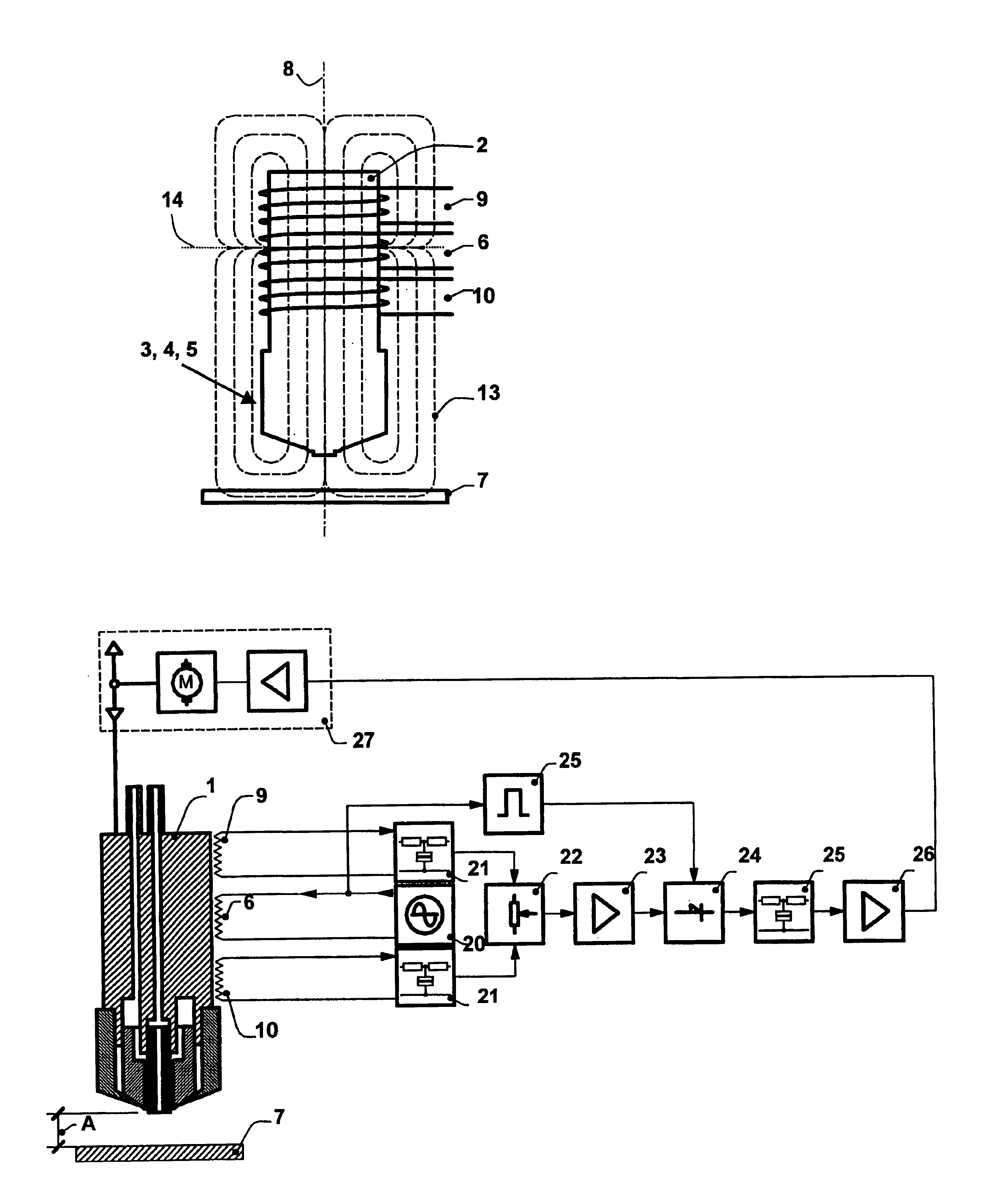
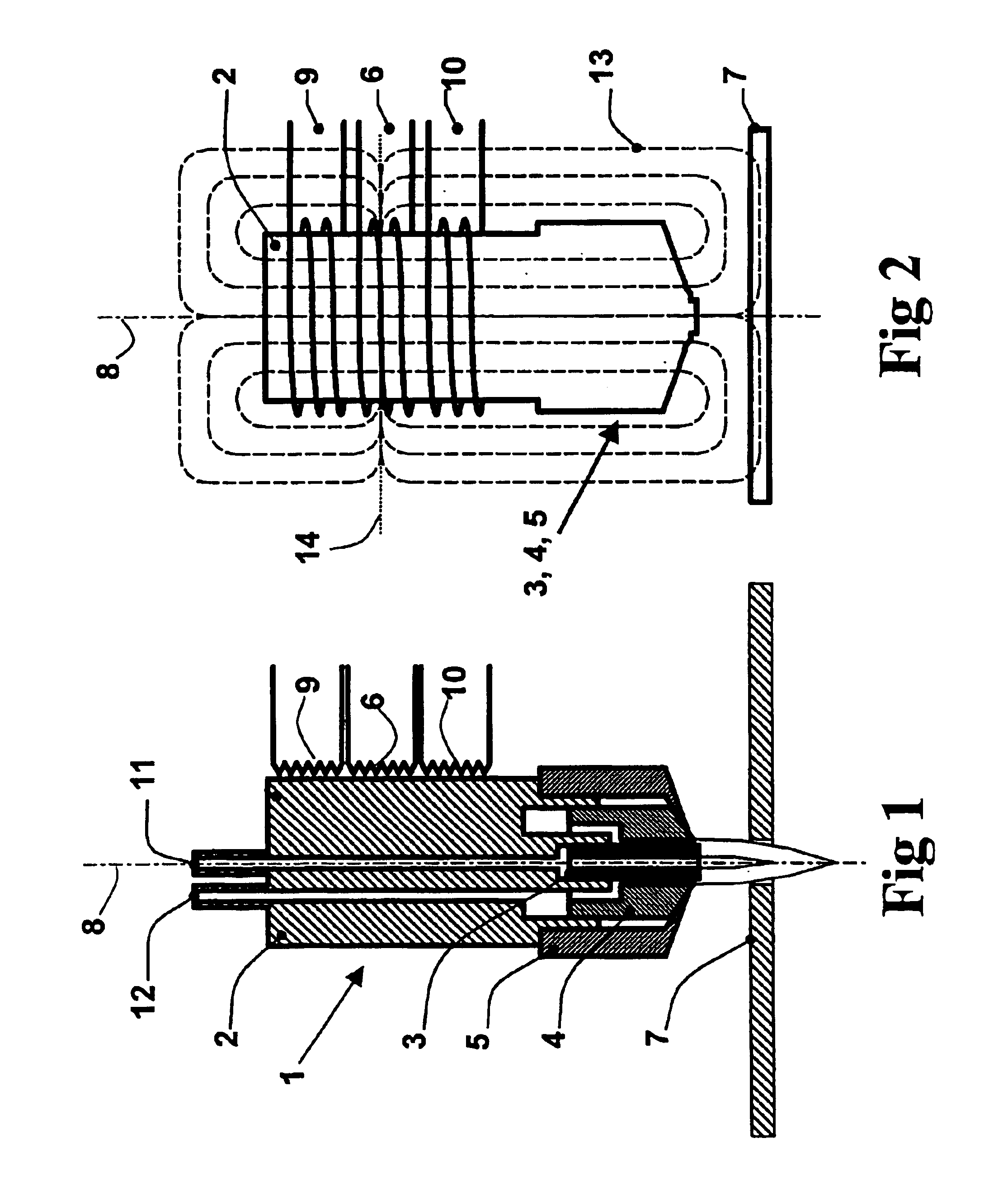
[0064]FIG. 1 shows an autogenous cutting torch which has reference numeral 1 assigned to it on the whole. The autogenous cutting torch 1 comprises a torch head 2 which has exchangeably mounted thereon, by means of a retaining cap 5, a cutting nozzle 3 and a heating nozzle 4 surrounding the cutting nozzle 3. It is essential for the present invention that the torch head 2 and at least one of the cutting or welding tools (3, 4, 5) have ferromagnetic properties. In the embodiment, both torch head 2 and cutting nozzle 3, as well as heating nozzle 4 and retaining cap 5 are made of a ferromagnetic iron-silicon alloy having 3 to 4% by wt. of silicon. All of these parts (2, 3, 4, and 5) are provided with a coating consisting of a dense corrosion-resistant material, such as chromium, titanium, chromium nitride (or a material with a similar action) for protection against oxidation.

[0065]The torch head 2 has a central axis 8 along which a line 11 extends for supplying cutting oxygen to the cutt...


PUM

PropertyMeasurementUnit
magnetic fieldaaaaaaaaaa
ferromagnetic propertiesaaaaaaaaaa
ferromagneticaaaaaaaaaa

Abstract

A thermal working tool (1) is movable along a workpiece surface (7) and includes a torch head (2) which has exchangeably mounted thereon cutting or welding tools (3; 4; 5) extending between the torch head (2) and the workpiece surface (7). A distance control for setting a predetermined working distance (A) between the working tool (1) and the workpiece surface (7) is carried out by a magnetic system, an alternating magnetic field being produced in a sensor body with ferromagnetic properties above the workpiece surface (7). The torch head (2) and at least one of the cutting or welding tools (3; 4; 5) contain ferromagnetic material and form at least part of the sensor body (2; 3; 4; 5). The magnetic field produced is sensed by two measuring coils, and is used for controlling the working distance (A).

Description

CROSS REFERENCE TO RELATED APPLICATION[0001]The present application claims priority from German Patent Application No. DE 103 32 422.4, filed Jul. 16, 2003.FIELD OF THE INVENTION[0002]The present invention refers to a method for thermally working a workpiece consisting of a ferromagnetic material by means of a thermal working tool which is moveable along a workpiece surface, wherein an alternating magnetic field is produced for controlling a working distance between the working tool and the workpiece surface, the magnetic field acting both in the area of the workpiece surface and in a sensor body with ferromagnetic properties above the workpiece surface, the magnetic field or changes thereof being sensed by means of a measuring device, and measurement signals of the measuring device being evaluated for controlling the working distance.[0003]Furthermore, the present invention refers to a thermal working machine for working a workpiece consisting of a ferromagnetic material, the machi...

Claims


Application Information

Patent Timeline
Patent Type & Authority Patents(United States)
IPC IPC(8): B23K9/08
CPCB23K9/08
Inventor FAUST, JOSEFFENNER, BURKHARDALBERT, HANS-JOACHIM
Owner MESSER CUTTING & WELDING GMBH
Why Eureka
Try Eureka