Switching power supply apparatus

a power supply and power supply technology, applied in the direction of electric variable regulation, process and machine control, instruments, etc., can solve the problems of wasteful power loss wasteful power loss, etc., and achieve the effect of reducing start-up time and high power use efficiency

Inactive Publication Date: 2005-06-07
SHARP KK
View PDF11 Cites 36 Cited by
  • Summary
  • Abstract
  • Description
  • Claims
  • Application Information

AI Technical Summary

Benefits of technology

[0081]With this configuration, at the start-up of the switching power supply apparatus, the current adjuster adjusts the current at the FB terminal of the PWM control IC. Thus, the PWM control IC makes the main switching device perform switching operation with a great on-state duty, and thereby reduces the start-up time. Moreover, on detecting the feedback signal, the start-up switcher starts to supply operating power to the signal level checker. Moreover, the CS terminal controller connects and disconnects the CS terminal of the PWM control IC to and from the negative power supply line according to the output signal of the signal level checker, and thereby turns on and off the PWM control IC. In this way, it is possible to realize burst switching operation with high power use efficiency.

Problems solved by technology

This causes wasteful power loss.
This causes wasteful consumption of the supply current, resulting in wasteful power loss.

Method used


Image

  • Switching power supply apparatus
  • Switching power supply apparatus
  • Switching power supply apparatus

Examples


first embodiment

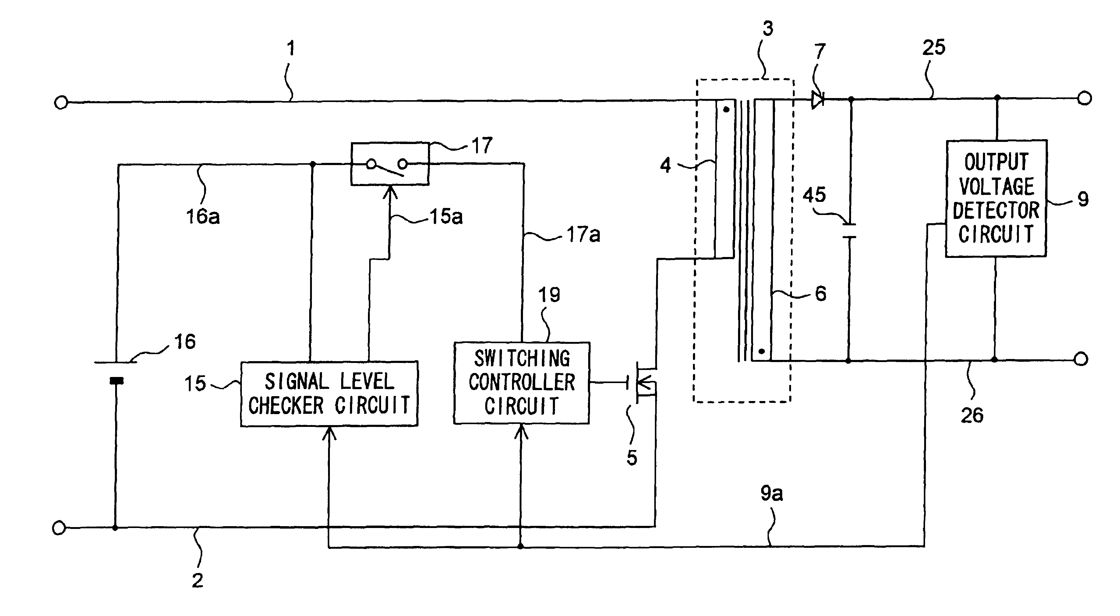
[0106]FIG. 1 is a circuit diagram of the switching power supply apparatus of a first embodiment of the invention.

[0107]In the switching power supply apparatus shown in FIG. 1, a transformer 3 has its primary coil 4 connected, at its one end, to a positive power supply line 1 and, at its other end, through a main switching device 5 to a negative power supply line 2. The main switching device 5 is realized with, for example, an FET (field-effect transistor). The transformer 3 has its secondary coil 6 connected, at its one end, through a diode 7 to an output line 25 and, at its other end, to an output line 26. Between the output lines 25 and 26, there are connected a capacitor 45 and an output voltage detector circuit 9. The output terminal of the output voltage detector circuit 9 is connected by way of a line 9a to the input terminal of a signal level checker circuit 15 and to the input terminal of a switching controller circuit 19 to feed each of them with a feedback signal.

[0108]An ...

second embodiment

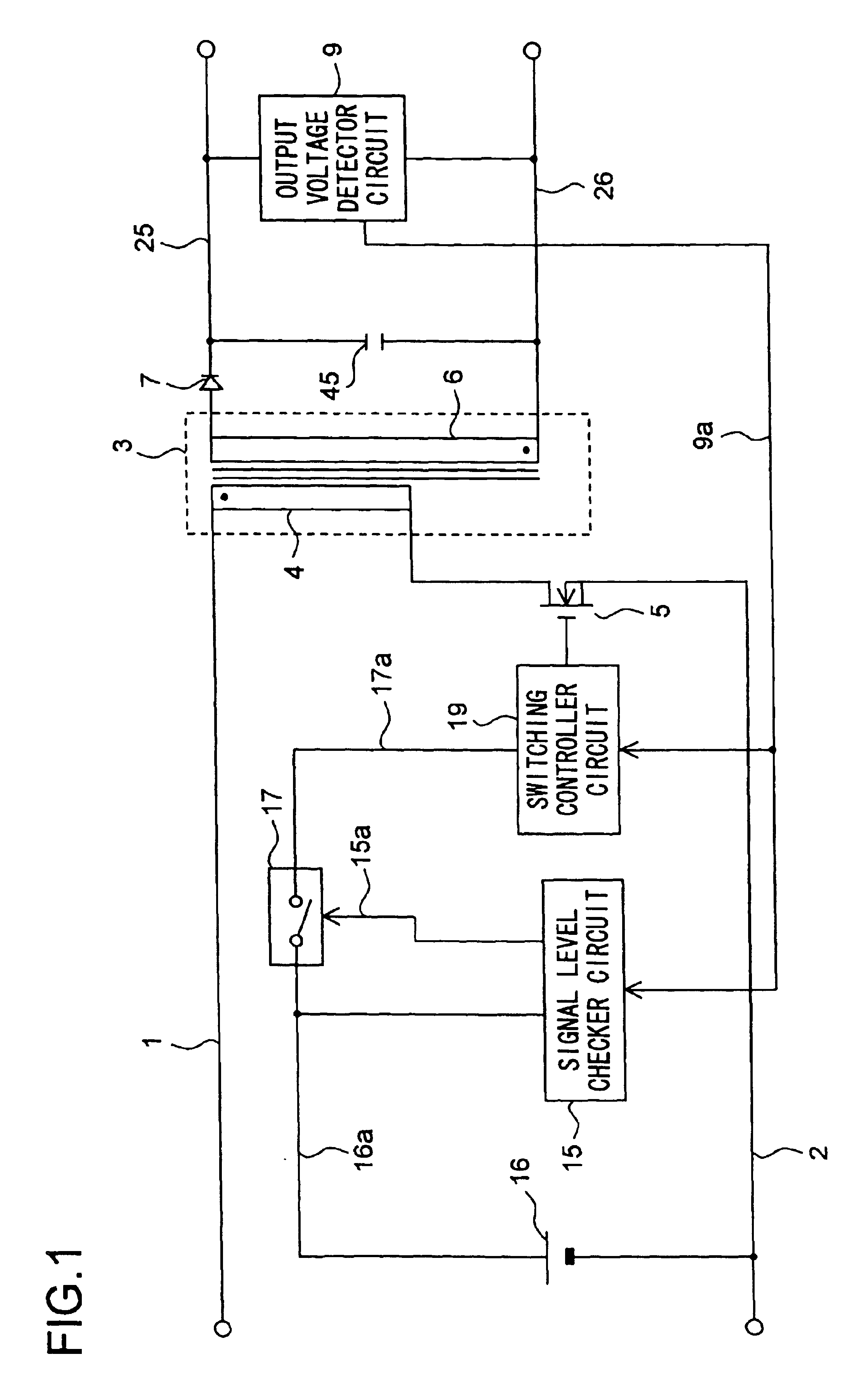
[0120]FIG. 2 is a circuit diagram of the switching power supply apparatus of a second embodiment of the invention.

[0121]In the switching power supply apparatus shown in FIG. 2, a transformer 3 has its primary coil 4 connected, at its one end, to a positive power supply line 1 and, at its other end, through a main switching device 5 to a negative power supply line 2. The transformer 3 has its secondary coil 6 connected, at its one end, through a diode 7 to an output line 25 and, at its other end, to an output line 26. Between the output lines 25 and 26, there are connected a capacitor 45 and an output voltage detector circuit 9.

[0122]The output voltage detector circuit 9 is composed of two serial circuits connected between the output lines 25 and 26, more specifically one composed of a photocoupler 20, a resistor 21, and a shunt regulator 22 and another composed of output voltage division resistors 23 and 24. The photocoupler 20 is composed of a photodiode 20a and a phototransistor 2...

third embodiment

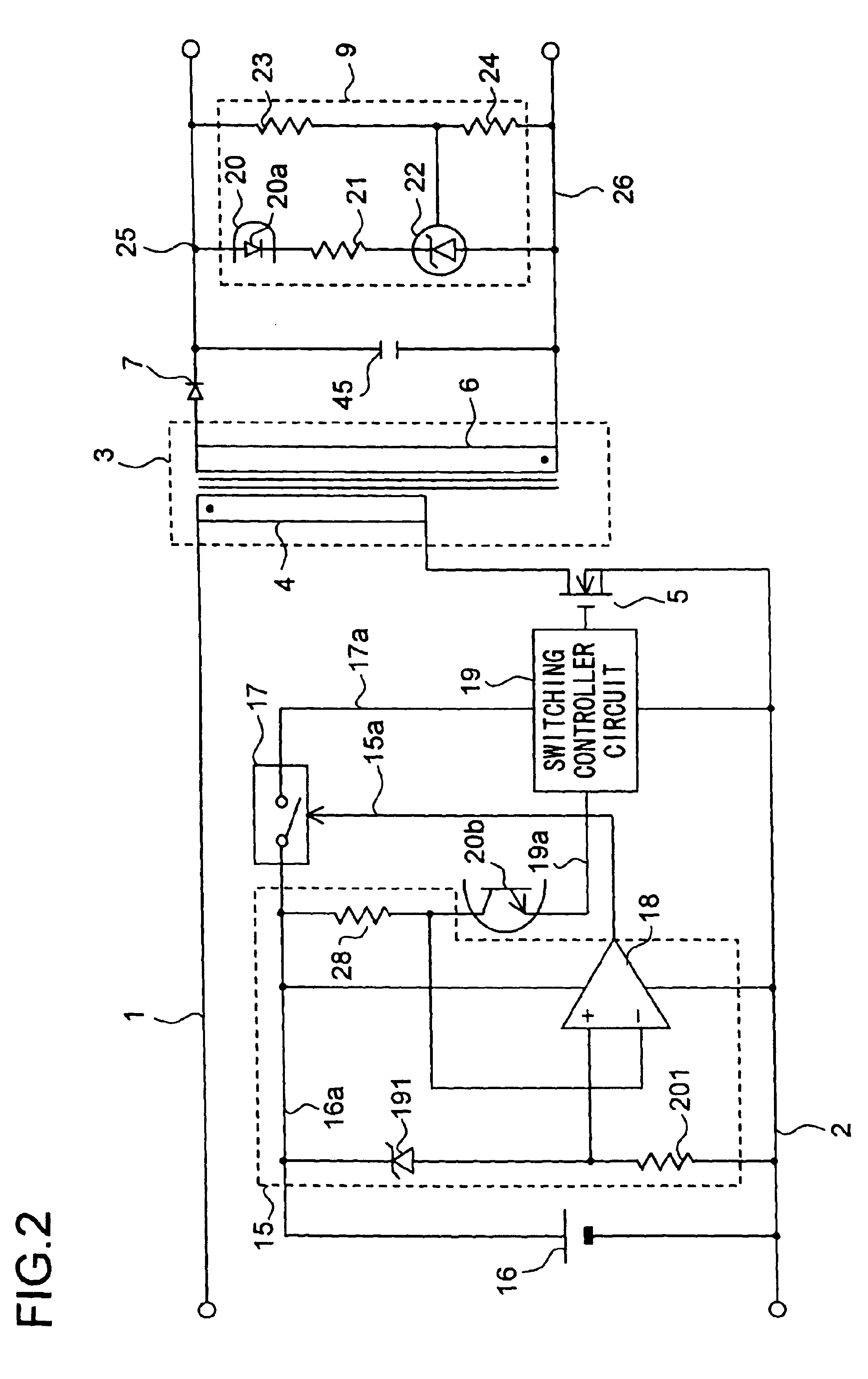
[0144]FIG. 3 is a circuit diagram of the switching power supply apparatus of a third embodiment of the invention. FIG. 3 is a circuit diagram showing the detailed circuit configuration of the operating power source 16 shown in FIGS. 1 and 2. In FIG. 3, such circuit components that find their counterparts in FIGS. 1 and 2 are identified with the same reference numerals, and their explanations will not be repeated.

[0145]In FIG. 3, the operating power of the switching controller circuit 19 is supplied thereto by way of a start-up current supply line 29a by way of which a start-up current is supplied from the positive power supply line 1 through a start-up resistor 29, or by way of a steady-state operating currant supply line 16a by way of which a voltage induced in a subsidiary coil 32 of the transformer 3 is supplied through a serial circuit composed of a plurality of diodes 30 and 31. The operating power of the signal level checker circuit 15 and the phototransistor 20b of the photoc...


PUM


Abstract

A switching power supply apparatus operates with less power consumption as a whole as a result of reduced power loss suffered while the switching operation of the main switching device is being stopped in burst switching control. Burst switching control is achieved by a signal level checker circuit 15 repeatedly turning on and off a switch circuit 17 provided in the line by way of which a switching controller circuit 19 is supplied with operating power. In burst switching control, when the switching operation of a main switching device 5 is being stopped, the supply of operating power to the switching controller circuit 19 is also stopped. This helps reduce the power loss suffered while the switching operation is being stopped, and thus helps reduce the power consumption of the apparatus as a whole.

Description

[0001]This nonprovisional application claims priority under 35 U.S.C. § 119(a) on Patent Application No.2002-249260 filed in JAPAN on Aug. 28, 2002, which is herein incorporated by reference.BACKGROUND OF THE INVENTION[0002]1. Field of the Invention[0003]The present invention relates to a switching power supply apparatus used as a direct-current power source in an electronic appliance.[0004]2. Description of the Prior Art[0005]A conventionally known example of such a switching power supply apparatus is disclosed, for example, in Japanese Patent Application Laid-Open No. H10-304658. The switching power supply apparatus disclosed in this publication is provided with a main switch that turns on and off a direct current applied to the primary coil of a transformer, a secondary-side rectifying / smoothing circuit that rectifies and smoothes the on / off signal induced in the secondary coil of the transformer so as to supply it as a main output signal, a subsidiary power source that rectifies...

Claims


Application Information

Patent Timeline
Patent Type & Authority Patents(United States)
IPC IPC(8): H02M3/335H02M3/24H02M3/28
CPCH02M3/33523Y02B70/16H02M2001/0032H02M1/0032Y02B70/10
Inventor KITANO, SABUROU
Owner SHARP KK
Why Eureka
Try Eureka