
Read channel apparatus and method for an optical storage system
a technology of optical storage system and read channel, which is applied in the field of optical storage system, can solve the problems of significant degradation of the performance of high-speed optical storage system, increase the complexity and cost, and reduce the sampling frequency, so as to reduce the clock rate of the read channel
- Summary
- Abstract
- Description
- Claims
- Application Information
AI Technical Summary
Benefits of technology
Problems solved by technology
Method used
Image

Examples
Embodiment Construction
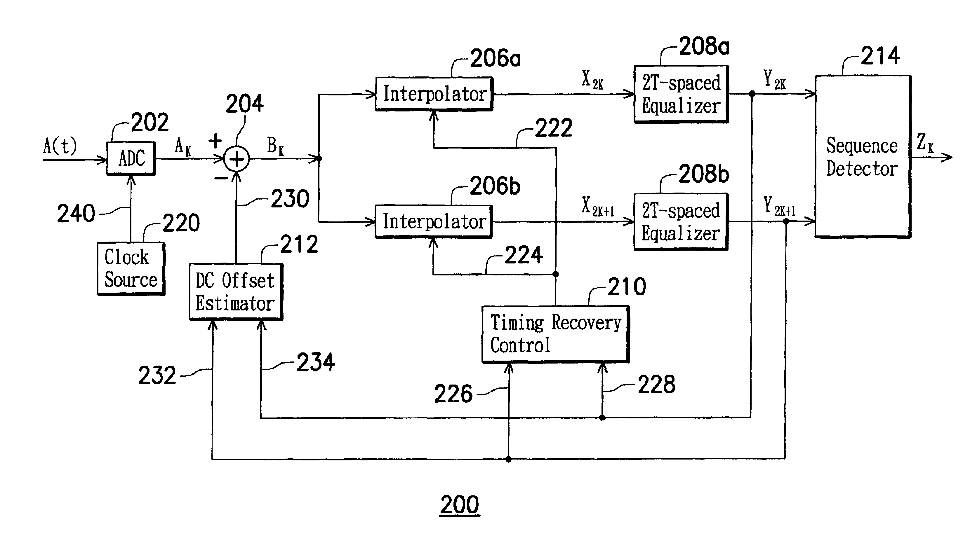
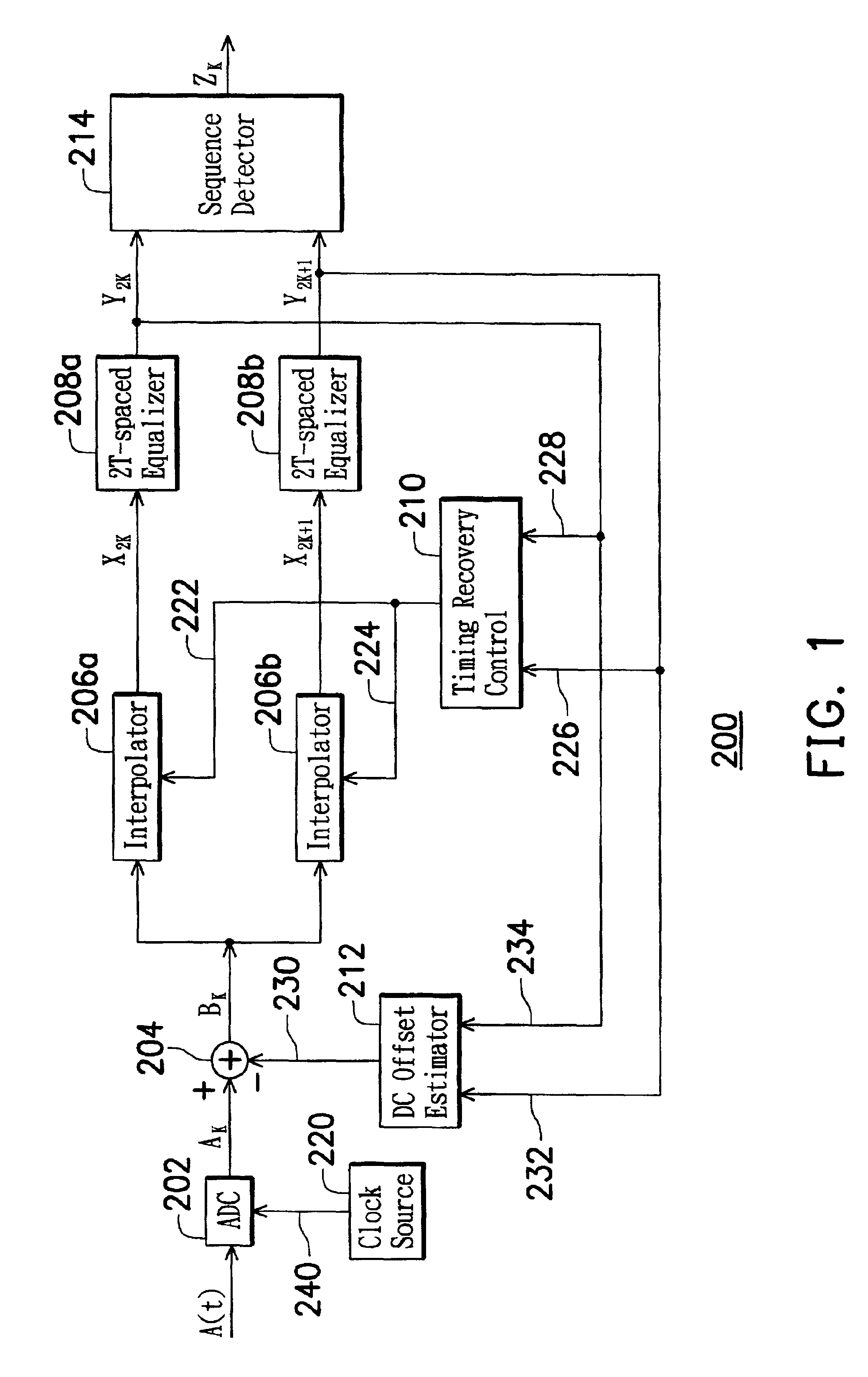
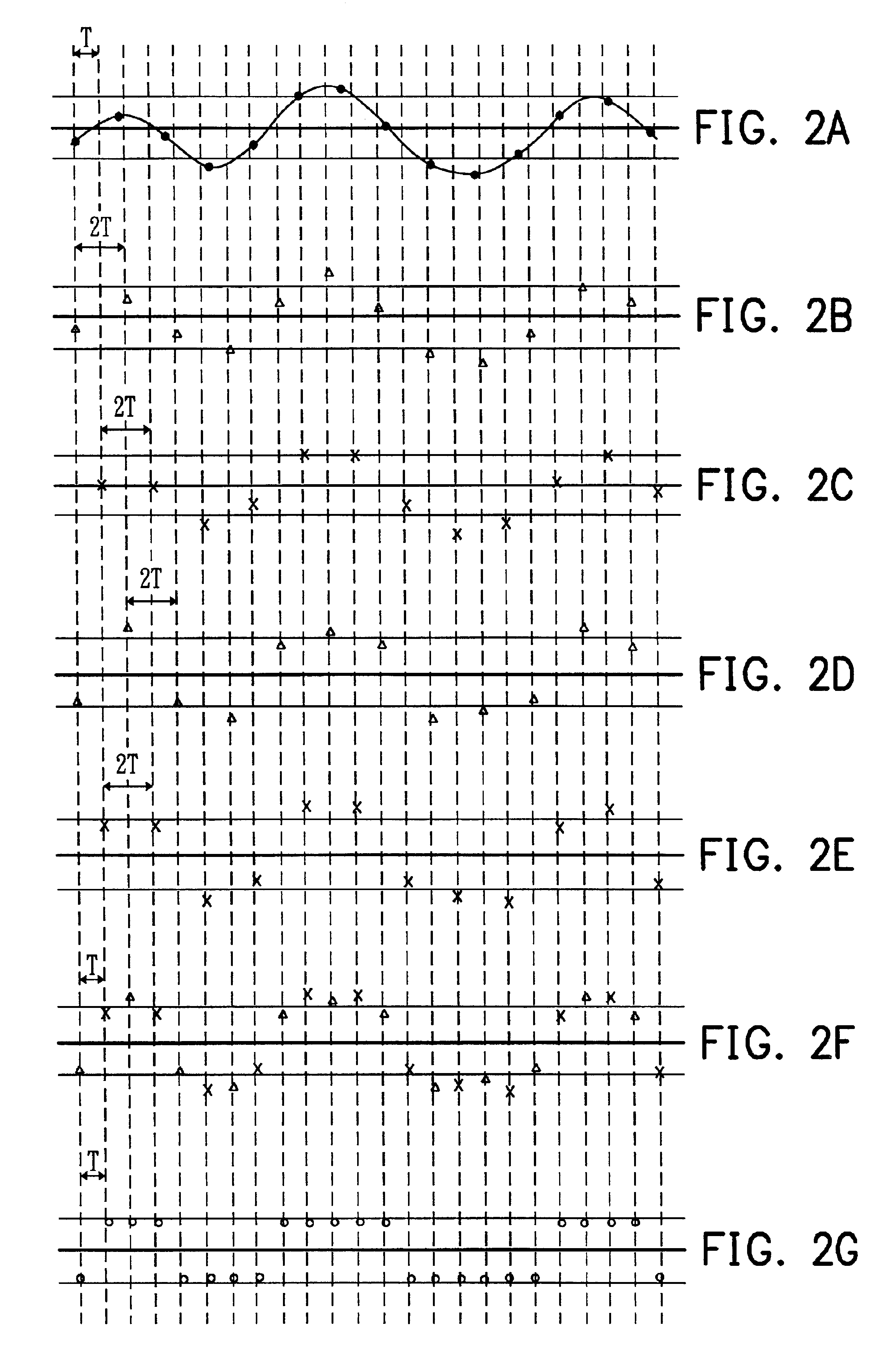
[0017]With reference to FIGS. 1 and 2A˜2G, the present invention will become more apparent from the following detailed description. A read channel apparatus 200 for reading data recorded on an optical storage system at a predetermined baud rate is shown in FIG. 1. The analog read signal A(t), generating from the optical storage system, is asynchronously sampled by a sampling device 202 (e.g., an analog-to-digital converter) to generate a sequence of asynchronous sample values AK. The sampling device 202 is clocked at a constant frequency fs by a sampling clock 240 generated by a clock source 220. The sequence of asynchronous sample values AK is related to the analog read signal A(t) as
AK={. . . , A(0), A(τ), A(2τ), . . . , A(kτ), . . .}
where k is an integer and τ=1 / fs. In FIG. 2A, the analog read signal is shown as a solid line, and the asynchronous sample values AK are shown as black dots. It should be noted that T, as depicted in FIGS. 2A˜2G, denotes the baud rate interval and 1 / T...
PUM
| Property | Measurement | Unit |
|---|---|---|
| run length | aaaaa | aaaaa |
| speed | aaaaa | aaaaa |
| frequency | aaaaa | aaaaa |
Abstract
Description
Claims
Application Information