

Low macrobending loss optical fiber
Inactive Publication Date: 2005-06-07
CORNING INC
View PDF12 Cites 30 Cited by
- Summary
- Abstract
- Description
- Claims
- Application Information
AI Technical Summary
Benefits of technology
[0018]The optical fibers of the present invention result in a number of advantages over prior art optical fibers. For example, the optical fibers of the present invention have both low macrobending losses and low cutoff wavelengths, and are suitable for the production of optical fiber couplers with low coupling loss. The optical fibers of the present invention also have low attenuation. The optical fibers of the present invention are also relatively insensitive to overclad mass, making them manufacturable in high yield. Additional features and advantages of the invention will be set forth in the detailed description which follows, and in part will be readily apparent to those skilled in the art from the description or recognized by practicing the invention as described in the written description and claims hereof, as well as in the appended drawings.
Problems solved by technology
Optical telecommunications systems are progressing toward higher speeds and longer span lengths, making the requirements for system components more and more arduous.
One such source is loss due to macrobending in the unfused regions of the optical fibers.
Conventional optical fibers tend to have relatively high macrobending losses, giving the assembled device an unacceptably high loss.
While there exist optical fibers having low macrobending loss, many of these fibers suffer from relatively high variability in manufacture.
In general, macrobending loss at a wavelength of 1550 nm increases with decreasing cutoff wavelength, making it difficult to provide a fiber having both low macrobending loss and low cutoff wavelength.
Conventional optical fibers do not provide for the manufacture of optical fiber couplers with the desired performance.
Method used
View moreImage
Smart ImageViewing Examples

Examples
example 1
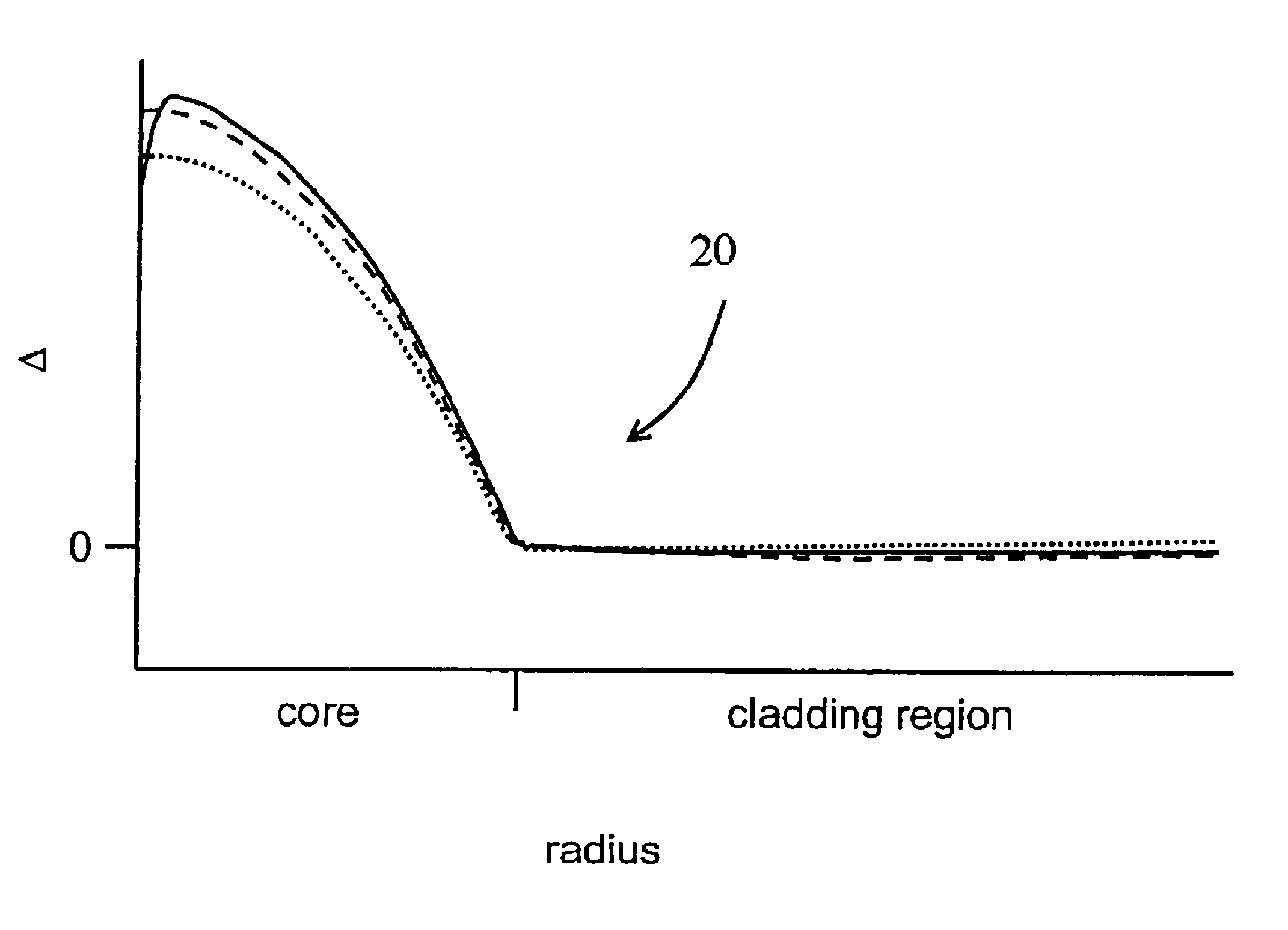
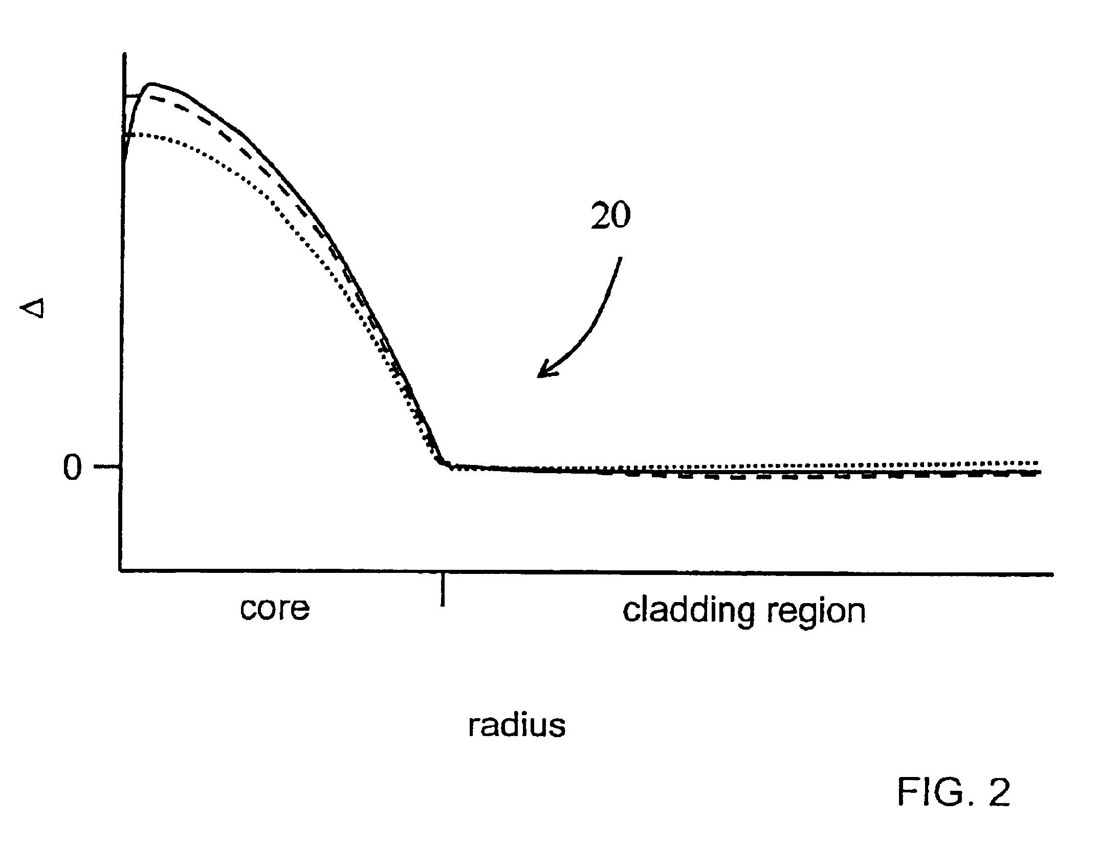
[0032]Conventional OVD processes were used to fabricate an optical fiber having the following profile:
[0033]α=2.10, with the α-profile beginning at the center of the core
[0034]core radius=3.6 μm
[0035]Δ=0.54%.
The optical fiber had the following properties:
[0036]cutoff wavelength: 932 nm
[0037]mode field diameter: 6.2 mm at 1060 nm; 9.1 mm at 1550 nm
[0038]MAC#: 6.6 at 1060 nm
[0039]Macrobending loss (single turn, 32 mm mandrel): 0.65 dB
[0040]Attenuation: 1.09 dB / km at 980 nm; 0.79 dB / km at 1060 nm; 0.25 dB / km at 1550 nm
[0041]Dispersion: 5.5 ps / nm-km at 1530 nm; 6.7 ps / nm-km at 1550 nm
[0042]Dispersion sensitivity parameter: 0.47 ps / nm-km.
Login to View More PUM
 Abstract
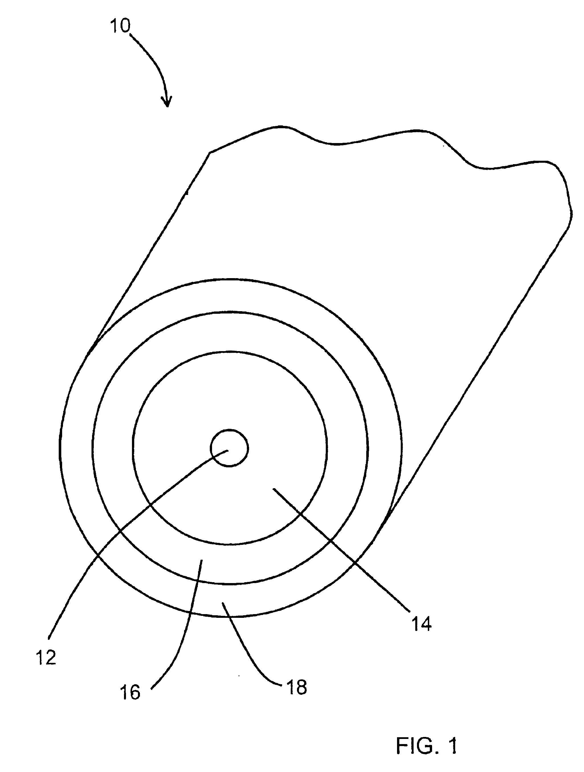
The present invention provides an optical fiber suitable for the manufacture of optical fiber couplers and having low macrobending loss, low cutoff wavelength, low attenuation, and low sensitivity to variations in overclad mass. One aspect of the present invention provides an optical fiber having a core having an index profile, the index profile of the core having a value of α of between about 1.7 and about 3.0; and a cladding region surrounding and in contact with the core, the cladding region having an outer radius of at least about 40 μm, wherein the optical fiber has a cutoff wavelength of between about 870 nm and about 970 nm, and a macrobending loss of below about 1 dB at a wavelength of 1550 nm when wrapped one turn around a 32 mm mandrel.
Description
CROSS-REFERENCE TO RELATED APPLICATIONS[0001]The present application claims the priority under 35 U.S.C. §119 (e) of U.S. Provisional Patent Application Ser. No. 60 / 384,625, filed May 31, 2002, which is entitled “LOW MACROBENDING LOSS OPTICAL FIBER” and is hereby incorporated by reference herein.BACKGROUND OF THE INVENTION[0002]1. Field of the Invention[0003]The present invention relates generally to optical communications, and more specifically to optical fibers having low macrobending loss suitable for splicing and for the fabrication of optical fiber couplers.[0004]2. Technical Background[0005]A high performance optical telecommunication system carries high data rates over long distances with no electronic regeneration. For example, rates of 10 Gb / s or more over unregenerated distances of three to five hundred kilometers have been achieved. A high performance system may employ high power signal lasers, optical amplifiers, dispersion compensation devices, optical switching devices...
Claims
Login to View More Application Information
Patent Timeline
 IPC IPC(8): G02B6/028G02B6/02
CPCG02B6/0281G02B6/02009G02B6/02271G02B6/02395G02B6/03611
InventorCHRISTOFF, WILLIAM R.JERIC, KRISTINA M.MARLOWE, DAVID T.MISHRA, SNIGDHARAJ K.
OwnerCORNING INC