Data recovery method and apparatus

a data recovery and clock technology, applied in the direction of color television with bandwidth reduction, synchronisation signal speed/phase control, television systems, etc., can solve the problems of latching data after an idle period, and it is difficult for a usb receiving device to recover the clock signal of the usb transmitting devi

Inactive Publication Date: 2005-06-14
INTEL CORP
View PDF8 Cites 34 Cited by
  • Summary
  • Abstract
  • Description
  • Claims
  • Application Information

AI Technical Summary

Problems solved by technology

This can be characterized as the problem, in digital communications of, transferring digital signals between multiple clock timing domains.
The USB Specification does not allow for a separate clock signal to be transmitted and this makes it difficult for a USB receiving device to adequately recover the clock signal of the USB transmitting device.
Another problem encountered in digital communications using USB is latching data after an idle period.

Method used


Image

  • Data recovery method and apparatus
  • Data recovery method and apparatus
  • Data recovery method and apparatus

Examples


Embodiment Construction

[0016]Embodiments of methods and systems for synchronizing data are described. In the following description, for purposes of explanation, numerous specific details are set forth to provide a thorough understanding of the present invention. It will be appreciated, however, by one skilled in the art, that the present invention may be practiced without these specific details. In other instances, structures and devices are shown in block diagram form. Furthermore, one skilled in the art can readily appreciate that the specific sequence in which methods are presented and performed are illustrative and it is contemplated that the sequences can be varied and still remain within the spirit and scope of the present invention.

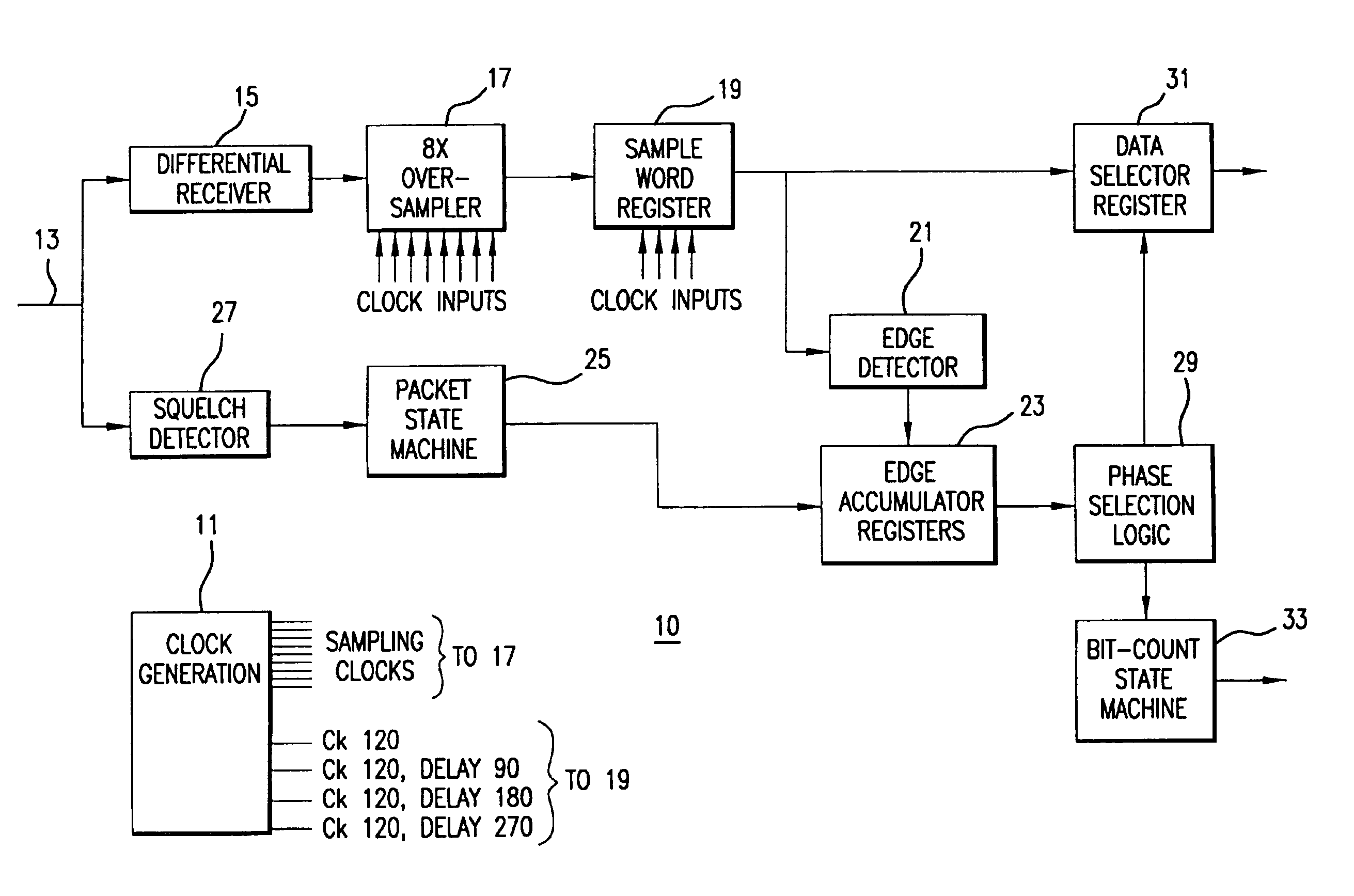
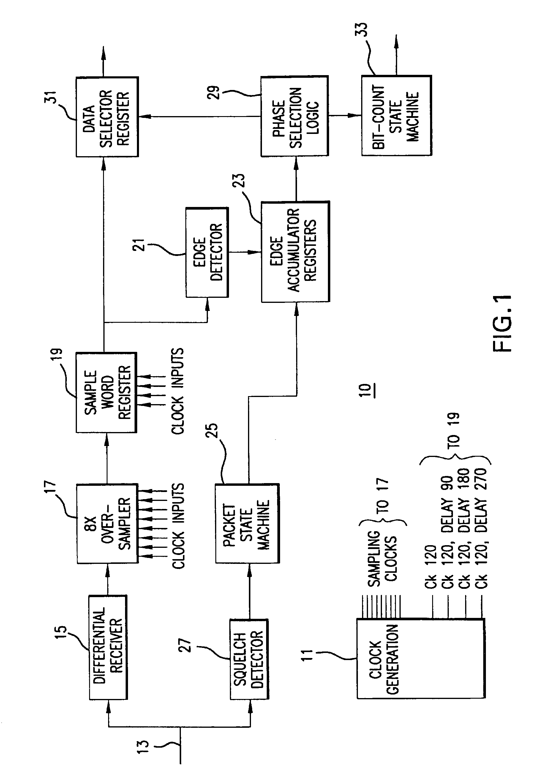
[0017]FIG. 1 is a block diagram of a receiver 10 for receiving digital data signals in accordance with an embodiment of the present invention. As an example, the receiver may comprise a Universal Serial Bus (USB) receiver. However, the method and apparatus of the present...


PUM


Abstract

In order to recover phase information, data transmitted at a first frequency is over-sampled using a clock at a second frequency, n times per bit time to obtain n samples. The n samples are used to detect the transitions between two logic levels in said transmitted data which are stored in groups of m sets of said n edge results which are, in turn output at a clock frequency which is the second frequency divided by m, for further processing.

Description

FIELD OF THE INVENTION[0001]Embodiments of the present invention relate to recovering clock and data information, from serial data.BACKGROUND OF THE INVENTION[0002]In some data communication arrangements, no separate clock signals are transmitted. This then requires recovering the clock at the receiving end in order to then recover the data. This can be characterized as the problem, in digital communications of, transferring digital signals between multiple clock timing domains. Multiple clock timing domains include the clock timing domain of a transmitting device as well as the clock timing domain of a receiving device. It is not unusual to transmit digital signals between clock timing domains having nearly the same underlying frequency clock, but different or varying phases with respect to each other.[0003]One such arrangement is the Universal Serial Bus (USB). The USB is a bus having electrical, mechanical, and communication characteristics that follows a protocol defined in “Uni...

Claims


Application Information

Patent Timeline
Patent Type & Authority Patents(United States)
IPC IPC(8): H04L7/00H04L7/04
CPCH04L7/046
Inventor LUEKER, JONATHAN C.WARREN, DEANOLIVER, KENNETH B.
Owner INTEL CORP
Why Eureka
Try Eureka