Apparatus and methods for facilitating wound healing

Inactive Publication Date: 2005-06-14
LA DIFFUSION TECHN FR
40 Cites 19 Cited by

AI-Extracted Technical Summary

Problems solved by technology

Patients that suffer from conditions which limit the flow of blood to the wound site are unfortunately not able to exhibit the normal wound healing process as described.
Factors that can negatively affect this normal wound healing process include diabetes, impaired circulation, infection, malnutrition, medication, and reduced mobility.
Other factors such as traumatic injuries and burns can also impair the natural wound healing process.
Poor circulation, for varying reasons, is the primary cause of chronic wounds such as venous stasis ulcers, diabetic ulcers, and decubitus foot ulcers.
The blood flow in this region of the legs in elderly or incapacitated patients can be very sluggish, leading to drying skin cells.
These skin cells are thus oxygen starved and poisoned by their own waste products and begin ...

Method used

[0033]Insulative element 26 prevents the flow of current between electrodes 22 and 24 above the wound surface such as by moisture trapped under the top overlay layer. Insulative element 26 may be composed of any high resistance material such as polythylene, poly(tetrafluoroethylene) (TEFLON), polyurethane, polyester, a hydrogel made to be an insulator or any other suitable insulative material. In addition, insulative element 26 may be formed of a material or designed to have gaps or openings within its body to prevent the flow of current or greatly increase the current resistance above the wound surface.
[0035]Conductive adhesive layers 52 and 54 are attached to the underside of electrode system 10, contacting electrodes 22 and 24, respectively and electrically insulative element 26. Adhesive layers 52 and 54 should be separated from each other by a suitable space or gap 58 to prevent short-circuiting of the electrodes. Adhesive layers 52 and 54 may be a hydrogel, fibrin, conductively transformed cyanoacrylates or can be comprised of any suitable electrically conductive material capable of attaching electrode system 10 to the skin and wound surfaces. Adhesive layer 52 can be arranged to distribute substantially the same voltage of electrode 22 to the entire surface of the wound. Similarly, adhesive layer 54 can be arranged to distribute substantially the same voltage of electrode 24 to the skin surrounding the wound. In another suitable approach, adhesive layer 52 can be arranged so that the center of adhesive layer 52 applies a voltage substantially similar to electrode 22 to the center of the wound and that the outer edge of adhesive layer 52 applies a voltage that is between the voltages of electrodes 52 a...

Benefits of technology

[0014]Furthermore, research conducted by Rafael Andino during his graduate tenure at the University of Alabama at Birmingham, also demonstrated that the presence of electrical fields (in this case induced by the application of pulsating electromagnetic fields) dramatically accelerated the healing rates of wounds created in an animal model. This research found that the onset and duration of the first two phas...

Abstract

An electrode system is provided that generates a current flow that envelops and permeates an entire wound site. The electrode system includes two electrodes that are shaped and oriented to cause the current to flow from one electrode through the wound to the other electrode. A first electrode is applied to the wound site and the second electrode encircles the first electrode and is applied to the skin surrounding the wound cite. The two electrodes may be mounted to an oxygen-permeable layer that provides support for the electrodes and allows the wound site to breathe. An electrically insulative element may be disposed between the two electrodes. A power supply, which may be local to or remote from the electrode system, is provided for applying a voltage potential across the electrodes. In another suitable embodiment, the two electrodes are comprised of oppositely charged polymers.

Application Domain

External electrodes

Technology Topic

Charged polymersVoltage +8

Image

  • Apparatus and methods for facilitating wound healing
  • Apparatus and methods for facilitating wound healing
  • Apparatus and methods for facilitating wound healing

Examples

  • Experimental program(1)

Example

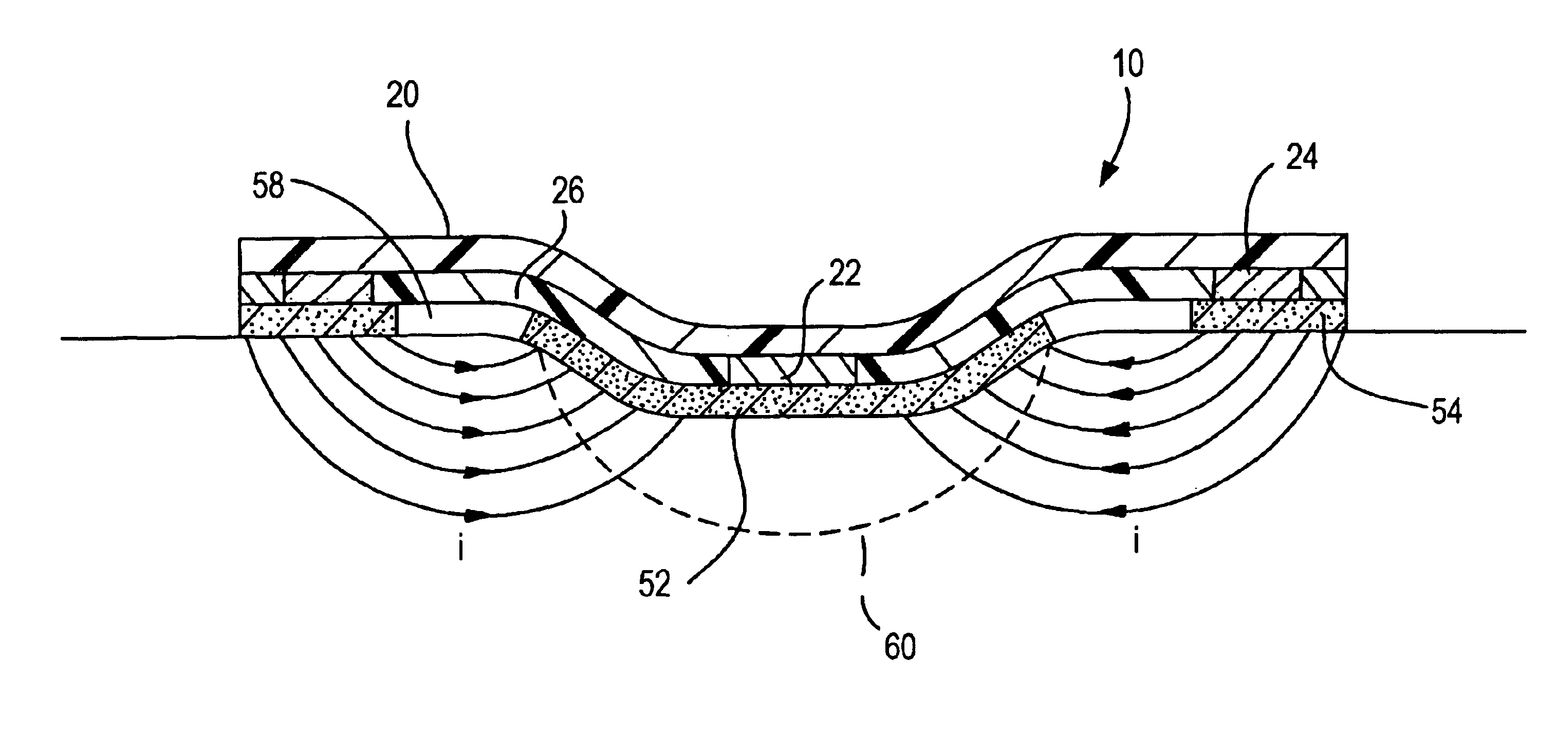
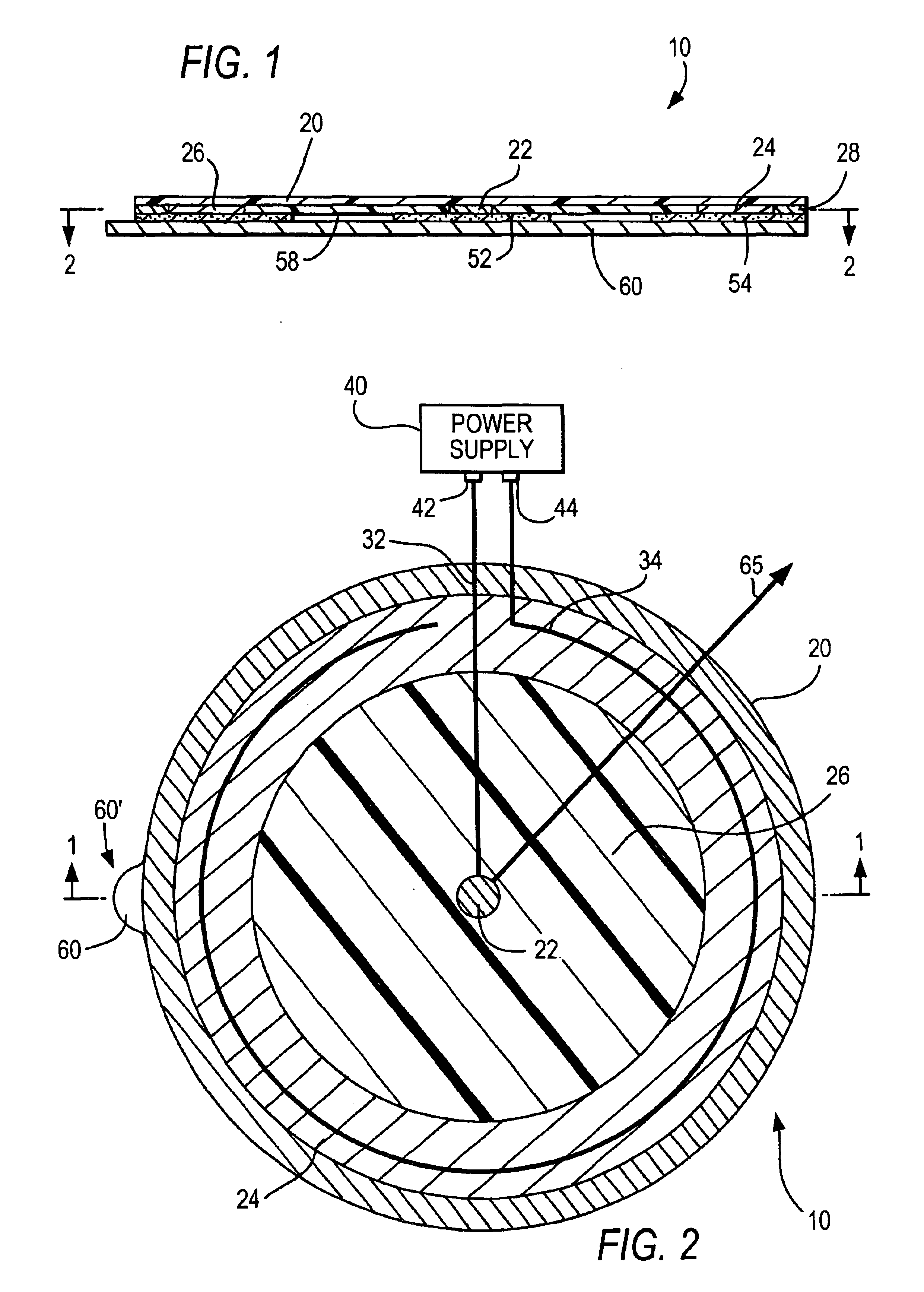
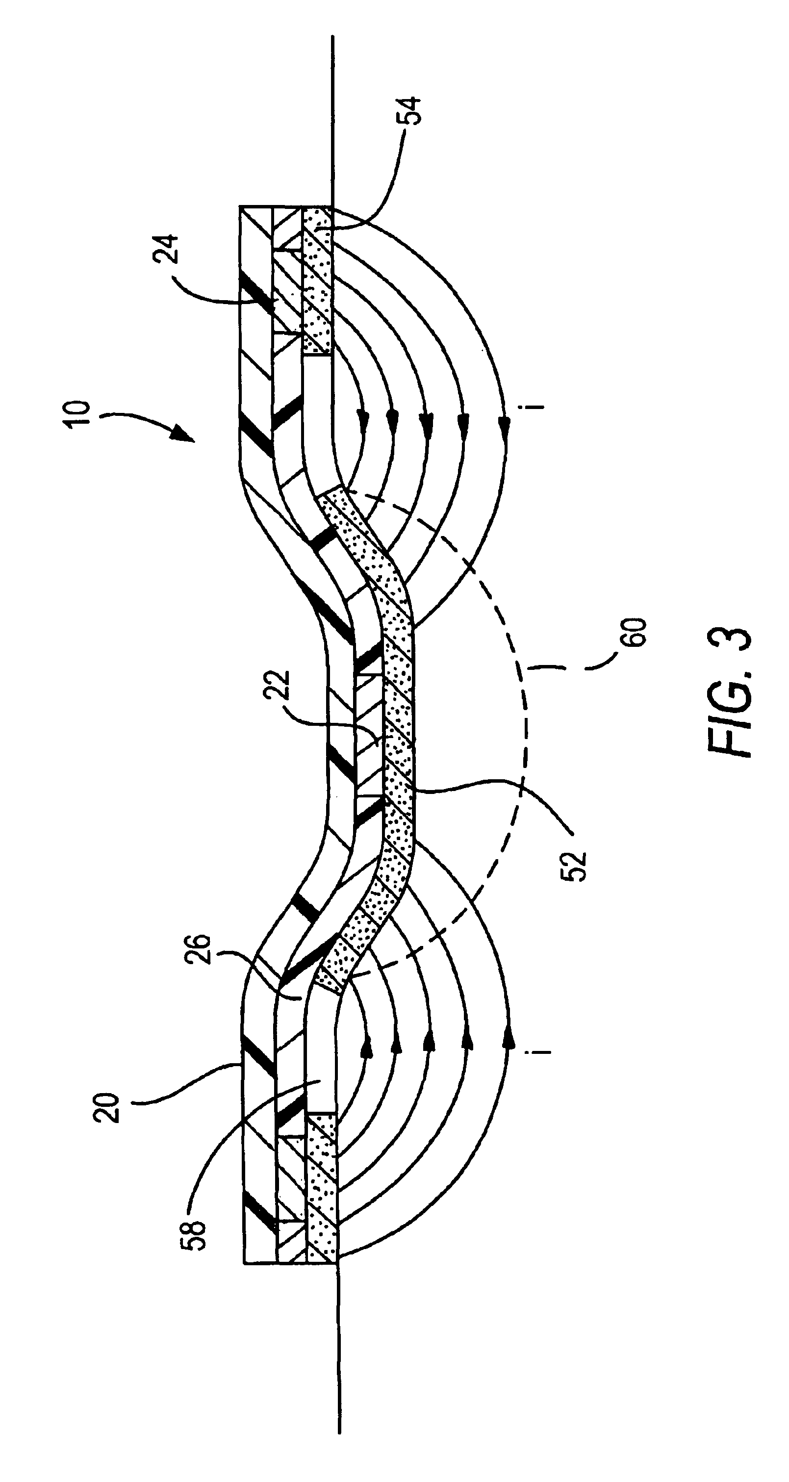
[0030]FIG. 1 is a cross-sectional view of electrode system 10. The view in FIG. 1 is taken along the line 1—1 of FIG. 2. FIG. 2 shows a simplified cross-sectional view of electrode system 10 taken alone the line 2—2 of FIG. 1. As illustrated in FIG. 1, electrode system 10 includes top overlay layer 20 to which electrodes 22 and 24, electrically insulative element 26, and end material 28 are attached. Electrode 22 is located towards the center of top overlay layer 20. Electrically insulative element 26 surrounds electrode 22 and electrode 24 surrounds electrically insulative element 26. Attached to the other side of electrodes 22 and 24, electrically insulative element 26, and end material 28 are adhesive layers 52 and 54. As illustrated in FIG. 2, electrically conductive lead 32 connects electrode 22 to terminal 42 of power supply 40 and electrically conductive lead 34 connects electrode 24 to terminal 44 of the power supply 40.
[0031]Top overlay layer 20 may serve several different purposes. First, top overlay layer 20 provides the mechanical integrity of electrode system 10, thus providing structural support for electrodes 22 and 24. Second, top overlay layer 20 should be flexible enough to allow electrode system 10 to conform to the contours of the skin surface to which it is adhered. Third, top overlay layer 20 should be oxygen permeable to allow the wound site to breathe. Finally, top overlay layer 20 should be water impermeable so that the wound site remains moist. In some embodiments, all of these characteristics may not be necessary. For example, a separate water impermeable layer may be used to keep the wound site moist. Top overlay layer 20 may be comprised of any suitable material or structure that exhibits these characteristics. For example, top overlay layer 20 may be comprised of a mesh structure of polypropylene, polyethylene, polyurethane, polytetrafluoroethylene (PTFE), or any other suitable material. In one embodiment, top overlay layer 20 can be electrically insulative to prevent current from flowing between electrodes 22 and 24, which are attached to top overlay layer 20. In another suitable embodiment, the adhesive or binding agent (not shown) used to adhere electrodes 22 and 24 to top overlay layer 20 can be electrically insulative to prevent current from flowing between electrodes 22 and 24.
[0032]Electrodes 22 and 24 may be thin metal, metallic paint or pigment deposition, metallic foil, conductive hydrogels, or any other suitable conductive material. Hydrogels are generally clear, viscous gels that protect the wound from dessicating. In one suitable approach, conductive hydrogels may be used as the material for electrodes 22 and 24 because of their permeability to oxygen and ability to retain water. Both oxygen and a humid environment is required for the cells in a wound to be viable. In addition, hydrogels can be easily cast into any shape and size. Various types of conductive hydrogels may be employed, including cellulose, gelatin, polyacrylamide, polymethacrylamide, poly(ethylene-co-vinyl acetate), poly(N-vinyl pyrrolidone), poly(vinyl alcohol), HEMA, HEEMA, HDEEMA, MEMA, MEEMA, MDEEMA, EGDMA, mathacrylic acid based materials, and siliconized hydrogels. PVA-based hydrogels are inexpensive and easy to form. The conductivity of such hydrogels can be changed by varying the salt concentration within the hydrogels. By increasing the salt concentration within a hydrogel, the conductivity of the hydrogel increases.
[0033]Insulative element 26 prevents the flow of current between electrodes 22 and 24 above the wound surface such as by moisture trapped under the top overlay layer. Insulative element 26 may be composed of any high resistance material such as polythylene, poly(tetrafluoroethylene) (TEFLON), polyurethane, polyester, a hydrogel made to be an insulator or any other suitable insulative material. In addition, insulative element 26 may be formed of a material or designed to have gaps or openings within its body to prevent the flow of current or greatly increase the current resistance above the wound surface.
[0034]End material 28 surrounds electrode 24. End material 28, in combination with the outer edge of top overlay layer 20, forms the outer edge of electrode system 10. End material 28 may be comprised of any suitable material flexible enough to allow electrode system 10 to conform to the contours of the skin surface to which it is adhered. In one embodiment, end material 28 may be composed of the same material as top overlay layer 20. In one suitable approach, end material 28 may be a part of and seamless with top overlay layer 20.
[0035]Conductive adhesive layers 52 and 54 are attached to the underside of electrode system 10, contacting electrodes 22 and 24, respectively and electrically insulative element 26. Adhesive layers 52 and 54 should be separated from each other by a suitable space or gap 58 to prevent short-circuiting of the electrodes. Adhesive layers 52 and 54 may be a hydrogel, fibrin, conductively transformed cyanoacrylates or can be comprised of any suitable electrically conductive material capable of attaching electrode system 10 to the skin and wound surfaces. Adhesive layer 52 can be arranged to distribute substantially the same voltage of electrode 22 to the entire surface of the wound. Similarly, adhesive layer 54 can be arranged to distribute substantially the same voltage of electrode 24 to the skin surrounding the wound. In another suitable approach, adhesive layer 52 can be arranged so that the center of adhesive layer 52 applies a voltage substantially similar to electrode 22 to the center of the wound and that the outer edge of adhesive layer 52 applies a voltage that is between the voltages of electrodes 52 and 54 to the outer edge of the wound. The voltage applied to the wound may be varied, for example, by varying the thickness of adhesive 52 or by any other suitable method.
[0036]As illustrated in FIG. 1, adhesive layer 52 extends beyond electrode 22. In another suitable arrangement, adhesive layer 52 may be the same size as or smaller than electrode 22. Adhesive layer 54 as illustrated is larger than electrode 24. In another suitable arrangement, adhesive layer 54 may be the same size as or smaller than electrode 24.
[0037]In another suitable embodiment, conductive adhesive layers 52 and 54 may be omitted from electrode system 10. In this embodiment, electrodes 22 and 24 are themselves adhesive and capable of attaching electrode system 10 to the wound site. Conductive hydrogels can be fashioned to have the requisite adhesive properties, thereby eliminating the need for separate adhesive layers. One type of highly conductive hydrogel that is sufficiently tacky and adhesive to adhere to the skin is described in U.S. Pat. No. 4,989,607 to Keusch et al. Electrodes 22 and 24 may be comprised of any suitable conductive adhesive material capable of attaching electrode system 10 to the wound site.
[0038]Backing layer 60 is attached to conductive adhesives 52 and 54 to protect the adhesive layer prior to the use of electrode system 10. Backing layer 60 may be peeled off of adhesives 52 and 54 to expose the adhesive layer prior to contacting electrode system 10 to the wound site. Backing layer 60 may protrude out from underneath top overlay layer 20 in one area, such as area 60′ as shown in FIG. 2, to allow the user to easily remove backing layer 60 from electrode system 10.
[0039]In use, electrode system 10 is positioned over the wound site such that electrode 22 is located at approximate the center of the wound site and adhesive layer 52 can be sized to cover the entire wound. Electrode system 10 is provided in a family of sizes appropriate for wounds of various sizes. Electrode 24 and adhesive layer 54 are generally in the shape of a ring and are located a distance away from electrode 22. In one arrangement, the diameters of the inner edges of electrode 24 and adhesive layer 54 are greater than the diameter of the wound. In another words, the size of the wound determines the minimum inner diameter of electrode 24 and adhesive layer 54. In another suitable arrangement, adhesive layer 52 can be sized to cover the inner portion of the wound and the inner diameters of the inner edges of electrode 24 and adhesive layer 54 may be the same or less than the size of the wound.
[0040]FIG. 3 is a cross-sectional view of electrode system 10 as applied to wound 60. As shown in FIG. 3, the pattern of current flow generated by electrode system 10 is toroidal in shape. A toroid is generally formed by rotating a circular disk about an axis, where the axis lies in the plane of the disk, but outside of the disk. Here, the pattern of current flow is similar to a semicircle rotated about an axis, where the axis lies in the plane of the semicircle and the axis is near the edge of the semicircle. The current generally flows tangential to the radial lines of the semicircle. Because electrode 24 surrounds electrode 22, the pattern of current flow is similar to the semicircular disk rotated completely around the axis. Therefore, the pattern of current flow is toroidal in shape. The pattern of current flow as illustrated in FIG. 3 would therefore generally be the same regardless of the angle of the cross-section cut through electrode system 10 with respect to reference direction 65 of FIG. 2. More specifically, as illustrated, electrode 22 is negatively charged and electrode 24 is positively charged. The lines of current flow extend from adhesive 54 through wound 60 to adhesive 52 in an arcuate shape. The lines of current pass through the entire wound 60, thereby enveloping and permeating the entire wound and the adjoining unwounded tissue. If the voltage that is applied to the wound from adhesive 52 is varied, as described above, then the current density at different portions of wound 60 can be increased or decreased accordingly. Electrode system 10 can produce a current density within the wound that is generally between 1 μA/cm2 and 10,000 μA/cm2. Depending on the size and nature of the wound, electrode system 10 may be configured to produce a current density within the wound that is less than of 1 μA/cm2 or greater 10,000 μA/cm2.
[0041]Referring to FIG. 2, conductive leads 32 and 34, which connect electrodes 22 and 24 respectively to power supply 40, may be comprised of metal, conductive ink or any other suitable conductive material. In one suitable arrangement, leads 32 and 34 are comprised of conductive carbon ink that is screened onto top overlay layer 20. In such an arrangement, electrodes 22 and 24 are formed in place over conductive leads 32 and 34, respectively.
[0042]Power supply 40 generates a voltage that is applied to electrodes 22 and 24 through leads 32 and 34, respectively. Power supply 40 may be configured to apply a voltage that is anywhere between 1 mV and 9 V. The resulting current flow that flows through the wound may be between 1 μA and 50 mA. Depending on the size and nature of the wound, power supply 40 may be configured to apply a voltage that is less than 1 mV or greater than 9 V. The resulting current flow may therefore be less than 1 μA or greater than 50 mA. Power supply 40 may be attached to the upper portion of top overlay layer 20 or any other suitable location on electrode system 10 or may be located remote from electrode system 10. In one suitable embodiment, power supply 40 is a battery. Power supply 40 may be any suitable battery such as an alkaline, nickel cadmium, or lithium battery. In one suitable arrangement, power supply 40 is a lithium polymer stack. The battery may be arranged so that terminal 42 is negative and terminal 44 is positive. Thus, electrode 22 functions as an anode and electrode 24 functions as a cathode. As described above, current will flow along outward radial lines from electrode 24 through the wound to electrode 22. In another suitable approach, the battery can be arranged so that terminal 42 is positive and terminal 44 in negative. In such an approach, the lines of current are reversed and directed outward from electrode 22 to electrode 24.
[0043]In another suitable embodiment, power supply 40 is comprised of electronic circuitry that is configured to provide a constant or varying voltage, a constant or varying current, or any other suitable electrical output. The current density within the wound site may therefore be constant or time varying. When power supply 40 varies the voltage or current, electrodes 22 and 24 may change polarities at a constant or at a time varying frequency. In another suitable electrical output, power supply 40 can be configured to pulse electrodes 22 and 24 to provide other possible therapeutic benefits.
[0044]In one suitable arrangement, the electrical circuitry can be configured to provide a constant current source using a current-to-voltage converter. The current to voltage converter may be probed at test points to check the current accuracy. The constant current source may be implemented with an operational amplifier (Op-amp). The Op-amp compares a precision voltage reference source to the output of a current-to-voltage converter and adjusts the output current until the reference and the converter are equal. The output voltage is limited to the battery voltage minus a certain predetermined amount used for operational purposes.
[0045]The circuit may be built with surface mount integrated circuits and other surface mount components and may be powered, for example, by lithium coin cell batteries.
[0046]The electrode system 10 herein described may not require a switch to be activated for current to commence flowing between electrodes 22 and 24. Rather, current may begin to flow following conductive contact of electrodes 22 and 24 to the wound site. Such contact completes a circuit between the electrodes and results in current flow between the electrodes. In another suitable embodiment, a switch may be located on electrode system 10 that may allow the user to engage and disengage power supply 40 to electrodes 22 and 24.
[0047]Electrode system 10 may contain within its circuitry a visual indicator to allow the user to determine whether or how well the electrode system is functioning. The visual indicator may be a light emitting diode (LED), a series of LEDs, a basic current meter, or any other suitable visual indicator.
[0048]FIG. 4 demonstrates a view of electrode system 10 placed over wound 60. In this embodiment, electrode system 10 is a disposable, one-time-use bandage that uses a battery and associated circuitry as power supply 40, which is attached to electrode system 10. Appropriate electrical parameters may be selected such that the current generated by the internal circuitry will last for a desired period of time. For example, the desired period of time may be at least as long as the typical amount of time a normal bandage is used on the wound. For users with chronic ulcers, this amount of time may typically be 1 to 2 days. Therefore, after electrode system 10 is activated by placement over the wound, an electrical current may last for 1 to 2 days. When it is time for electrode system 10 to be replaced, a new electrode system will be applied and the treatment will continue as required by the individual user and the type of wound present.
[0049]While electrode system 10 has been described as being generally circular in shape, it is understood that electrode system 10 may also be provided in other shapes as well. For example, electrode system 10 may be provided in an oval shape, rectangular shape, triangular shape, or any other suitable shape. The resulting pattern of current flow would therefore be similar to the toroidal shape described above which has been stretch from a circle to an oval shape, rectangular shape, triangular shape, or any other suitable shape of electrode system 10. Electrode system 10 is preferably provided in different shapes appropriate for wounds of different shapes. For example, if the wound is a long gash wound, a rectangular or oval shaped electrode system may be the appropriate shape for the wound. In one suitable approach, a preferred electrode system shape for a wound is a shape that will allow adhesive 52 to cover the entire wound and that will minimize the amount of area that adhesive 52 covers exterior to the wound. This will maximize the current flow through the wound.
[0050]In another suitable electrode system embodiment, electrodes 22 and 24 are electrically charged polymers. In this embodiment, power supply 40 and leads 32 and 34, as illustrated in FIGS. 1 and 2 are not required. In addition, top overlay layer 20 may not be required and electrodes 22 and 24 may be separately applied. Electrodes 22 and 24 can be oppositely charged polymers (e.g., hydrogel or any other suitable material for holding a charge) of sufficient differential voltage potential and of sufficient charge densities to cause a current to flow between the electrodes. In one suitable arrangement, electrode 22 is negatively charged and electrode 24 is positively charged. This would cause current to flow through the wound to negative electrode 22 from positive electrode 24. In another suitable arrangement, electrode 22 is positively charged and electrode 24 is negatively charged. This would cause current to flow from positive electrode 22 through the wound to negative electrode 24.
[0051]The foregoing is merely illustrative of the principles of this invention and various modifications can be made by those skilled in the art without departing from the scope and spirit of the invention.

PUM

no PUM

Description & Claims & Application Information

We can also present the details of the Description, Claims and Application information to help users get a comprehensive understanding of the technical details of the patent, such as background art, summary of invention, brief description of drawings, description of embodiments, and other original content. On the other hand, users can also determine the specific scope of protection of the technology through the list of claims; as well as understand the changes in the life cycle of the technology with the presentation of the patent timeline. Login to view more.

Similar technology patents

Method for Manufacturing Semiconductor Device

InactiveUS20080050921A1high mass productivityshort amount of time
Owner:SEMICON ENERGY LAB CO LTD

Electronic circuit building block

InactiveUS7203074B1inexpensive and convenientshort amount of time
Owner:INTELLECT LAB

Method to Cold-Start Fuel Cell System at Sub-Zero Temperatures

ActiveUS20070224462A1short amount of timelow battery power requirement
Owner:NUCELLSYS

Voice recognition system

ActiveUS20150221308A1short amount of timeimprove accuracy
Owner:DENSO CORP

Method for detecting defects in a substrate having a semiconductor device thereon

InactiveUS20080172196A1less complexshort amount of time
Owner:SAMSUNG ELECTRONICS CO LTD

Classification and recommendation of technical efficacy words

  • short amount of time

Method of sorting dice by speed during die bond assembly and packaging to customer order

ActiveUS6984533B1improvement in packaging flowshort amount of time
Owner:XILINX INC

Network switch assembly, network switching device, and method

ActiveUS7304940B2ability of to maintainshort amount of time
Owner:WORLD WIDE PACKETS INC

Method For Fire Suppression

InactiveUS20080115949A1short amount of timelow oxygen concentration
Owner:AIR PROD & CHEM INC

Method to Cold-Start Fuel Cell System at Sub-Zero Temperatures

ActiveUS20070224462A1short amount of timelow battery power requirement
Owner:NUCELLSYS
Why Eureka
Try Eureka