Synchronization circuit and synchronization method

a synchronization circuit and synchronization method technology, applied in the direction of generating/distributing signals, digital storage, instruments, etc., can solve the problems of inability to correct phase comparison, signal waveform to be transferred is deformed, and the tracking ability when the phase is deviated to a large extent is bad, so as to achieve simplified structure, less jitter, and high response characteristic

Inactive Publication Date: 2005-06-21
RENESAS ELECTRONICS CORP
View PDF12 Cites 44 Cited by
  • Summary
  • Abstract
  • Description
  • Claims
  • Application Information

AI Technical Summary

Benefits of technology

[0009]An object of the present invention is to provide a synchronization circuit and a synchronization method in which both response characteristic and stability are satisfied with a simplified structure. Another object of the present invention is to provide a synchronization circuit and a synchronization method to obtain a synchronization signal which is stabilized for the frequency up to the higher frequency. The aforementioned and the other objects and novel features of the present invention will become apparent from the description of the present specification and the accompanying drawings.

Problems solved by technology

The technology described in the patent document 1 has the problem that tracking ability when the phase is deviated to a large extent is bad because the coarse adjustment and fine adjustment are performed based on the integration of phase comparison pulse.
Moreover, here rises also a problem that when the frequency becomes higher, the signal waveform to be transferred is deformed and correct phase comparison becomes impossible.

Method used


Image

  • Synchronization circuit and synchronization method
  • Synchronization circuit and synchronization method
  • Synchronization circuit and synchronization method

Examples


Embodiment Construction

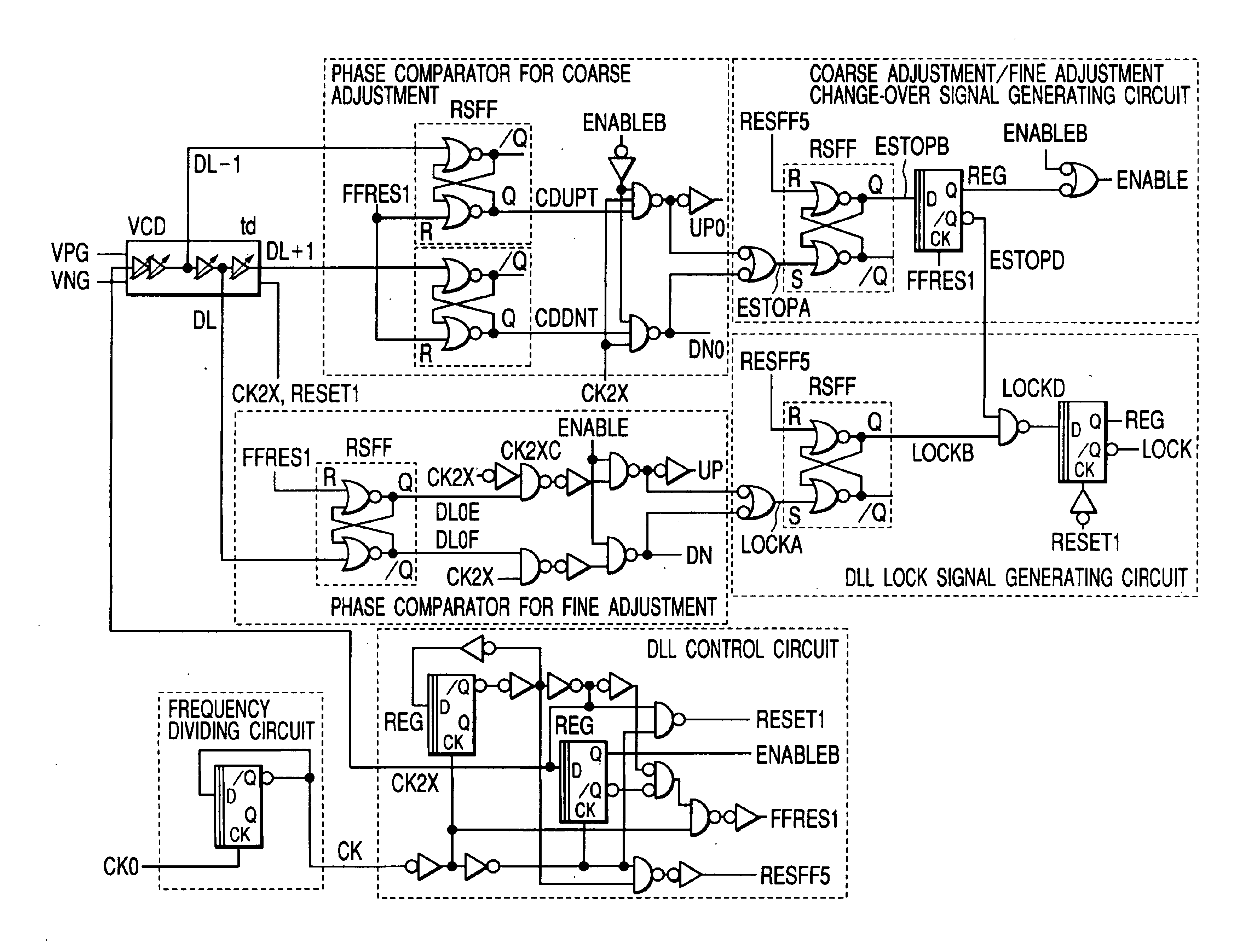
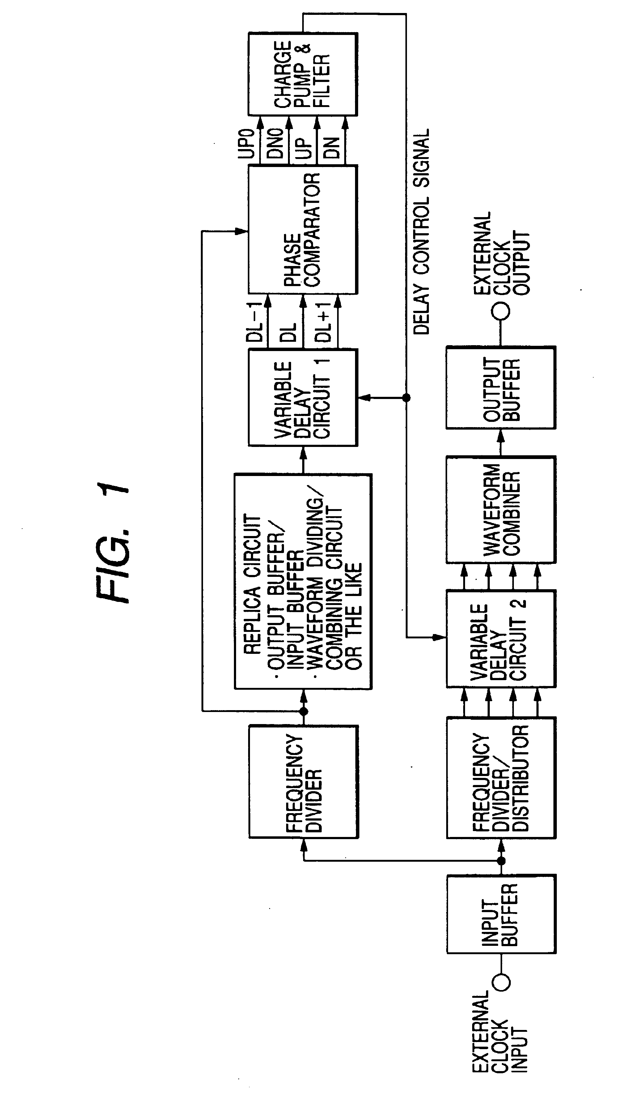
[0029]FIG. 1 illustrates a block diagram of an embodiment of a DLL (Delay Locked Loop) of the present invention. The DLL circuit of this embodiment forms an external clock output synchronized with an external clock input and is constituted by a DLL section and a delay section to delay an external clock input. In this embodiment, various ideas are comprised to realize highly accurate phase control operation and delay operation in the frequency up to the still higher frequency band.

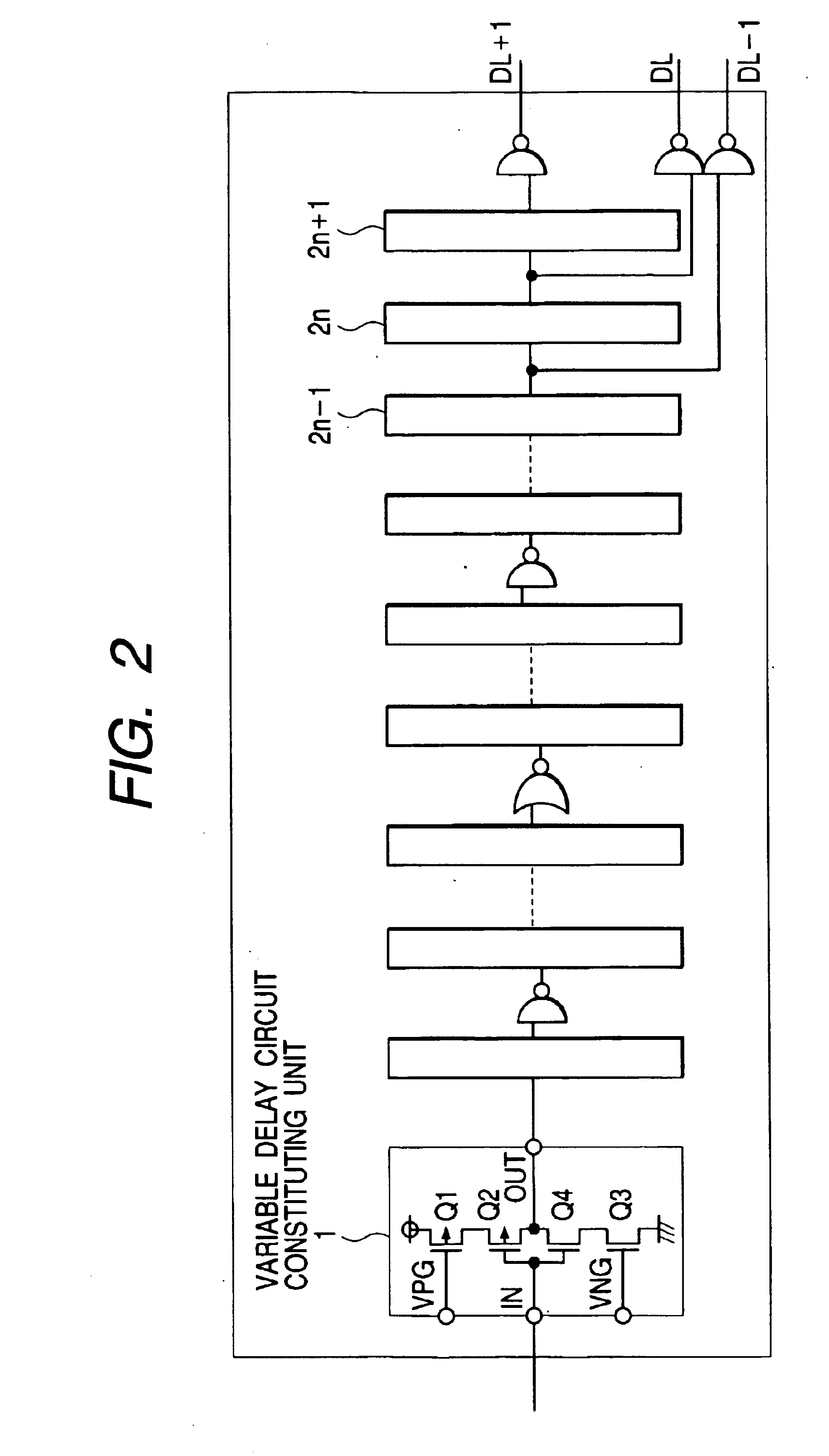
[0030]In this embodiment, the phase control is performed by clearly selecting coarse adjustment range and fine adjustment range in the DLL section. In more practical, a delay signal DL−1 in one preceding stage of the variable delay stage and a delay signal DL+1 in one subsequent stage thereof are formed for the standard delay signal DL in the variable delay circuit 1 of the DLL section. Namely, in the variable delay circuit 1, a unit variable delay stage is constituted by a plurality of stages, the standard...


PUM

PropertyMeasurementUnit
delay timeaaaaaaaaaa

Abstract

Phase synchronization is achieved by forming a first pulse to be synchronized with a reference pulse, a second pulse leading in phase for a certain period relative to said first pulse and a third pulse delayed in phase for a certain period from said first pulse; comparing said reference pulse with said first pulse in a first comparing; comparing said reference pulse with said second pulse and said third pulse in a second comparing; and forming a control voltage by giving priority to a comparison output of said second comparing with respect to a comparison output of said first comparing, matching the phase of said reference pulse with the phrase of said second pulse or said third pulse, and matching, after said matching of phases, the phrase of said reference pulse with the phase of said first pulse by forming said control, voltage from the comparison output of said first comparing.

Description

BACKGROUND OF THE INVENTION[0001]The present invention relates to a synchronization circuit and a synchronization method and the technology, for example, which can be effectively utilized for the phase synchronization technology to be applied to a DLL (or PLL) circuit provided in semiconductor integrated circuit device.[0002]An example of the PLL circuit which can continuously change over coarse adjustment and fine adjustment is disclosed in the Japanese Published Unexamined Patent Application No. Hei 08(1996)-307254. Moreover, an example of a frequency multiplying circuit including a combining circuit is disclosed in the Japanese Published Unexamined Patent Application No. 11(1999)-004145.[0003][Patent Document 1][0004]Japanese Published Unexamined Patent Application No. Hei 08(1996)-307254[0005][Patent Document 2][0006]Japanese Published Unexamined Patent Application No. Hei 11(1999)-004145SUMMARY OF THE INVENTION[0007]The technology described in the patent document 1 has the prob...

Claims


Application Information

Patent Timeline
Patent Type & Authority Patents(United States)
IPC IPC(8): G06F1/06G11C11/407H03L7/087H03K5/13H03L7/06H03L7/081H03L7/00H03L7/08H03L7/16H04L7/04G11C11/4076H03L7/089H03L7/095H03L7/099H03L7/107H03L7/191
CPCH03L7/0805H03L7/0812H03L7/087H03L7/191H03L7/095H03L7/0995H03L7/0891H03L7/0816H03L7/0818A63C17/068B29C65/02B29C66/7212
Inventor MITSUMOTO, KINYA
Owner RENESAS ELECTRONICS CORP
Why Eureka
Try Eureka