
Method of and apparatus for extending signal ranges of digital images

Active Publication Date: 2005-06-21
PROTEINSIMPLE +1
View PDF26 Cites 41 Cited by
  • Summary
  • Abstract
  • Description
  • Claims
  • Application Information

AI Technical Summary

Benefits of technology

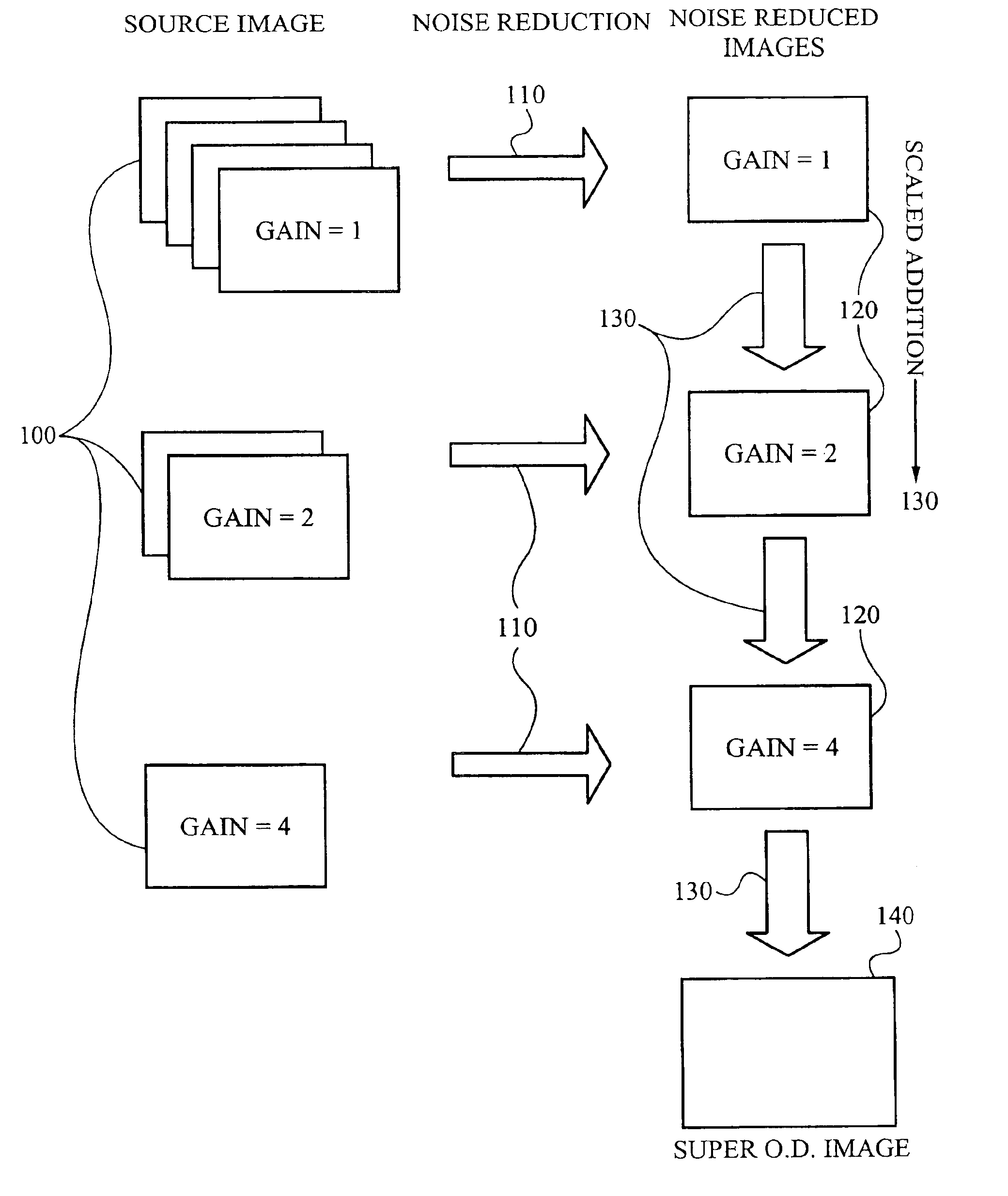
[0016]In one aspect of the present invention, a method of extending a signal range of a digital image comprises duplicating the digital image such that a plurality of source images are formed, each of the source images including a predetermined number of the duplicated digital images, scaling each of the plurality of source images, wherein the scaling is based upon a gain value assigned to each of the plurality of source images, reducing a noise component in each of the plurality of source images, such that a plurality of noise reduced images are formed corresponding to each of the plurality of source images and adding the plurality of noise reduced images. The method further comprises receiving the digital image in a sensor and sending the digital image to a computer and outputting the sum of the plurality of noise reduced images to an output device.
[0019]In the apparatus of this aspect, each of the plurality of noise reduced images includes a single noise reduced image. The gain value for each of the plurality of source images is 2x, such that the highest gain value will not exceed 2x where x is an integer less than or equal to 10, and each successive gain value Will have a value of 2x−1. The predetermined number of duplicated digital images in each of the plurality of sources images is determined by 2x, wherein x is equal to 0 for the source image having the highest gain value, and each successive source image will have a number of duplicate digital images according to 2x+1. A user can set the highest gain value and the number of the plurality of source images. The reducing means reduces the noise component in each of the plurality of source images, the computer averages each of the plurality of source images.
[0021]The computer includes means for duplicating the digital image such that a plurality of source images are formed, each of the source images including a predetermined number of the duplicated digital images, means for scaling each of the plurality of source images, wherein the scaling means are based upon a gain value assigned to each of the plurality of source images, means for reducing a noise component in each of the plurality of source images, such that a plurality of noise reduced images are formed corresponding to each of the plurality of source images and means for adding the plurality of noise reduced images.
[0022]The apparatus also comprises means for receiving the digital image in a sensor and means for sending the digital image to a computer and means for outputting the sum of the plurality of noise reduced images to an output device. Also, each of the plurality of noise reduced images includes a single noise reduced image. The gain value for each of the plurality of source images is 2x, such that the highest gain value will not exceed 2x where x is an integer less than or equal to 10, and each successive gain value will have a value of 2x−1. The predetermined number of duplicated digital images in each of the plurality of sources images is determined by 2x, wherein x is equal to 0 for the source image having the highest gain value, and each successive source image will have a number of duplicate digital images according to 2x+1. A user can set the highest gain value and the number of the plurality of source images. When the reducing means reduces the noise component in each of the plurality of source images, the computer averages each of the plurality of source images. The sensor is a charge coupled device or a complementary metal oxide semiconductor. The output device is a video monitor or a printer.
[0024]In the article of manufacture of this aspect, each of the plurality of noise reduced images includes a single noise reduced image. The gain value for each of the plurality of source images is 2x, such that the highest gain value will not exceed 2x where x is an integer less than or equal to 10, and each successive gain value will have a value of 2x−1. The predetermined number of duplicated digital images in each of the plurality of sources images is determined by 2x, wherein x is equal to 0 for the source image having the highest gain value, and each successive source image will have a number of duplicate digital images according to 2x+1. A user can set the highest gain value and the number of the plurality of source images. When the reducing means reduces the noise component in each of the plurality of source images, the computer averages each of the plurality of source images.
[0025]In yet another aspect of the present invention, an apparatus for extending a signal range of a digital image comprises a storage media for storing a computer application, a processing unit coupled to the storage media and a user interface coupled to the processing unit such that a user can duplicate the digital image to form a plurality of source images, scale each of the plurality of source images, reduce a noise component in each of the plurality of source images and add the plurality of source images.

Problems solved by technology

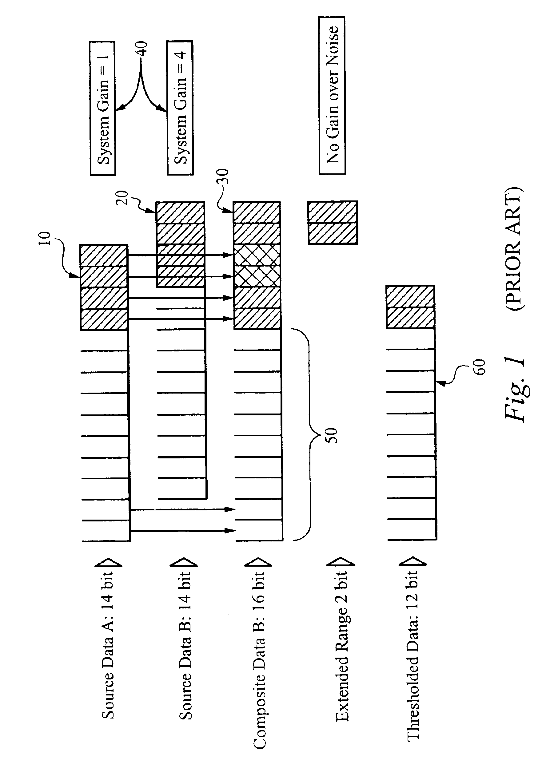
Despite improvements in sensor technology, the light signal or brightness range of naturally occurring and constructed subjects often exceeds the nominal output range of instruments available to detect photons.
In addition, the nominal output data of the sensor includes some amount of noise that reduces the useful signal range.
While these methods may generate visually pleasing images, they do not address the demands of scientific imaging.
Losing the linear relationship between object brightness and output data value limits this method's application to scientific quantification.
Thus, the potential for extended dynamic range is limited by the scaling of noise in the composite image.
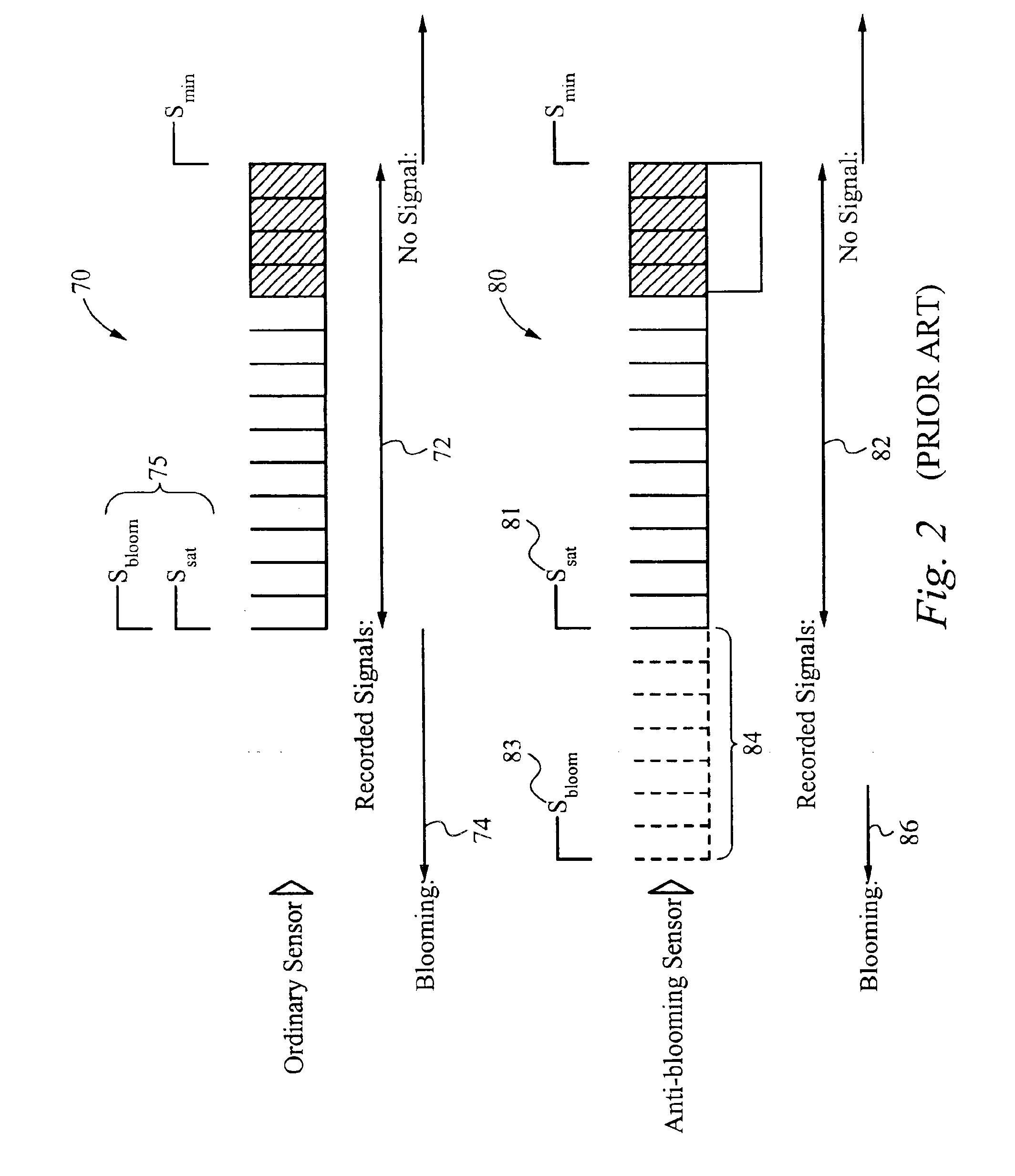
After reaching SSat for a certain pixel, an ordinary sensor is not only unable to record more signal, but is also unable to contain the excess electrons.
Therefore any additional signal received at that pixel will result in electrons overflowing to unsaturated neighboring pixels.
Since the overflow signal contaminates the target signal, data is lost when blooming occurs.

Method used


Image

  • Method of and apparatus for extending signal ranges of digital images
  • Method of and apparatus for extending signal ranges of digital images
  • Method of and apparatus for extending signal ranges of digital images

Examples


embodiment

Imaging Apparatus Embodiment

[0072]In the preferred embodiment of the present invention depicted in FIG. 5, the method is applied in conjunction with an imaging apparatus 300. Among other functions, this imaging apparatus 300 maintains a constant rate of light emission from the subject by placing subject, illumination, and sensing means within a data acquisition enclosure 301. Given the broad application of this method for extending signal range, the imaging apparatus 300 may be of diverse constructions.

[0073]In the preferred embodiment, the data acquisition enclosure 301 need not be light tight to achieve this goal, as long as the data acquisition enclosure 301 can prevent fluctuations in the rate of light emission on the time scale required for data acquisition. One example of a data acquisition enclosure is the ChemiImages 5500 scientific imaging system (IS-5500, Alpha Innotech Corporation, San Leandro). This scientific imaging system is equipped with a light-tight portable darkro...


PUM


Abstract

The invention is a method and apparatus to extend the signal range of a digital image beyond the nominal sensor or data format range. The method and apparatus automatically acquires a scaled series of source data, applies noise reduction to the source data, and constructs a scaled composite with usable signal ranges greater than that of the individual data sources. Applied to digital images, the invention permits presentation and analysis of all signals from a subject in a single composite or an image resulting from the method and apparatus of the present invention. The present invention overcomes two defects in prior art systems: increased noise in the resultant composite image arising from rescaling of component images and dependence on evaluating image content to determine image scaling. Because this invention can be automated, it can be applied in numerous fields requiring high throughput.

Description

RELATED APPLICATION(S)[0001]This Patent Application claims priority under 35 U.S.C. §119(e) of the co-pending U.S. Provisional Patent Application, Ser. No. 60 / 404,752, filed Aug. 21, 2002, and entitled “METHOD AND APPARATUS TO EXTEND SIGNAL RANGE.” The Provisional Patent Application, Ser. No. 60 / 404,752, filed Aug. 21, 2002, and entitled “METHOD AND APPARATUS TO EXTEND SIGNAL RANGE” is also hereby incorporated by reference in its entirety.FIELD OF THE INVENTION[0002]The present invention relates generally to the field of digital imaging applications. More particularly, the present invention relates to the field of extending the useful optical density (OD) range in digital imaging samples.BACKGROUND OF THE INVENTION[0003]In many digital imaging applications, light from a subject can be represented in an image. Despite improvements in sensor technology, the light signal or brightness range of naturally occurring and constructed subjects often exceeds the nominal output range of instru...

Claims


Application Information

Patent Timeline
IPC IPC(8): H04N5/217G06T5/50H04N5/353H04N5/355H04N5/361H04N5/365
CPCH04N5/2355G06T5/50H04N23/741
Inventor WATSON, JR., ROBERT M.KANG, JOHN J.
Owner PROTEINSIMPLE
Learn More