Multiple grating optical waveguide monitor

a monitor and optical waveguide technology, applied in the field of optical monitors, can solve the problems that the cost/performance combination of prior art devices does not meet the desired target, and achieve the effect of improving the resolution and performance of the monitoring devi

Inactive Publication Date: 2005-06-21
LUCENT TECH INC
View PDF8 Cites 39 Cited by
  • Summary
  • Abstract
  • Description
  • Claims
  • Application Information

AI Technical Summary

Benefits of technology

[0007]The need remaining in the prior art is addressed by the present invention, which relates to an optical monitor utilizing waveguide gratings to redirect ce...

Problems solved by technology

In many newer applications, such as measuring optical signal-to-noise ratios (OSNRs) of tightly-spaced dense WDM (“DWDM”) channels (e.g., 50 Ghz and closer spacings), extended dynamic range measurements, simultaneous monitoring of ultrawid...

Method used


Image

  • Multiple grating optical waveguide monitor
  • Multiple grating optical waveguide monitor
  • Multiple grating optical waveguide monitor

Examples


example

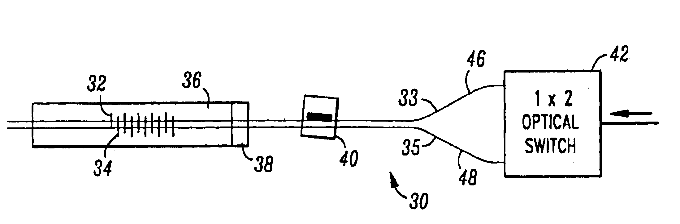
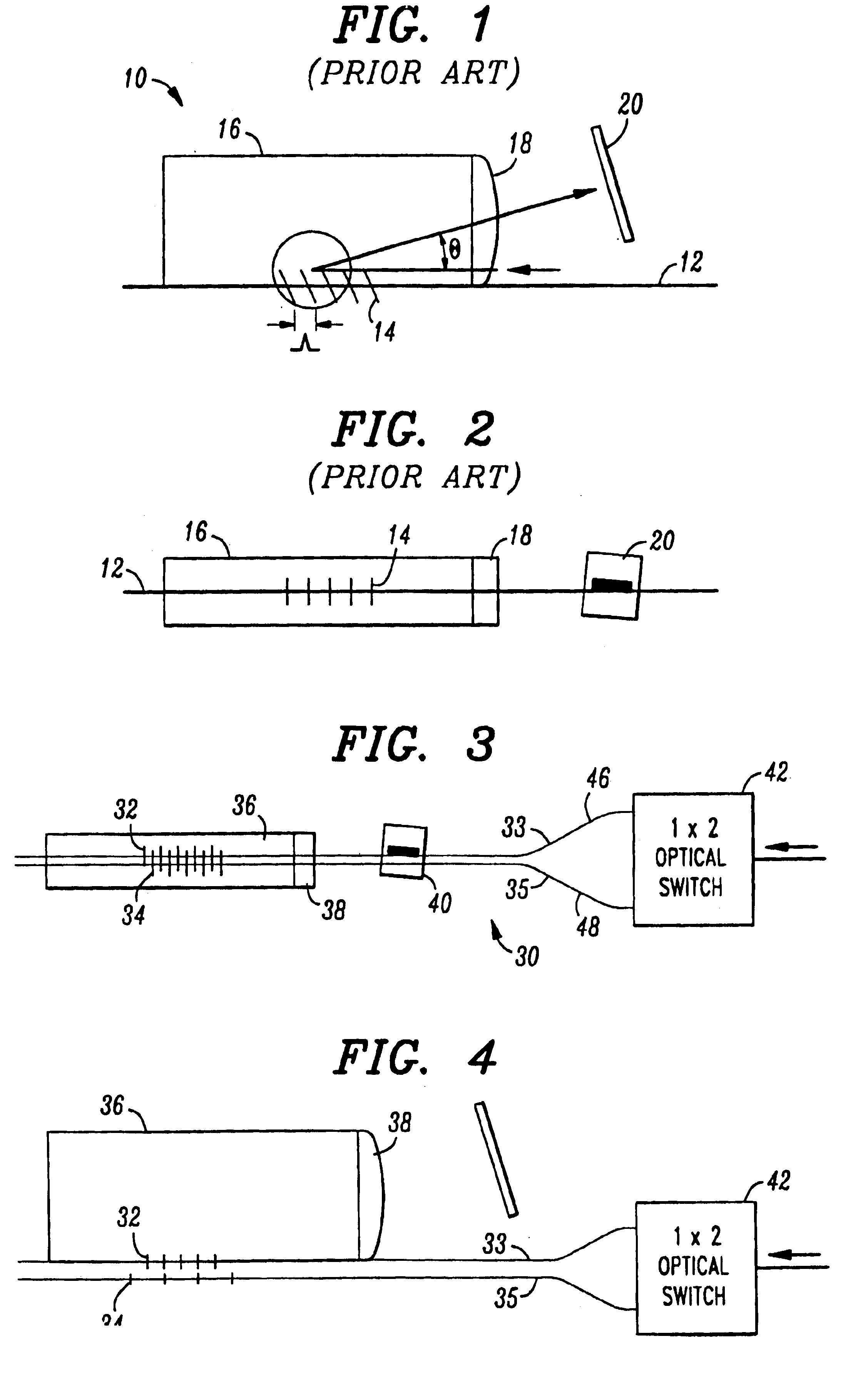
[0033]We have experimentally demonstrated the multiple grating optical waveguide monitor as depicted in FIGS. 3 and 4. A pair of unchirped fiber blazed Bragg gratings 32 and 34, with center wavelengths of 1547 nm and 1575 nm, respectively, were used as the dispersive elements. The blaze angles θ1 and θ2 were chosen to be equal at a value of 9°, such that the wavelength 1547 nm from grating 32 and wavelength 1575 nm from grating 34 emanated at the same angle relative to the fiber axes, namely 18°. The gratings were photolithographically written in a conventional single mode silica-based fiber using phase masks. The lengths of the gratings were approximately 10 mm. The strengths of the gratings were such that ˜20% of the single mode light at the center wavelengths were tapped out of the fibers. To achieve the fiber-to-block coupling, the gratings were bonded to a fused silica glass block (n=1.44 at 1550 nm) with an optically transparent, closely index-matching (n=1.56) adhesive. Glass...


PUM


Abstract

An optical monitoring arrangement utilizes the properties of a blazed Bragg grating to redirect a portion of an optical signal out of the axial path and into a detecting device. A plurality of blazed Bragg gratings are utilized, each having unique properties, to increase the robustness of the monitor. In particular, by utilizing a plurality of N gratings, the bandwidth of the monitor may be increased N-fold (assuming no overlap in wavelength between gratings). Alternatively, an improvement in resolution can be obtained by utilizing a narrower bandwidth and measuring N times the number of raw data points within that bandwidth. A combination of increase in bandwidth and resolution may be obtained by a comprise between these two extremes. Chirped blazed gratings may also be employed.

Description

[0001]This application is a continuation-in-part of prior application Ser. No. 09 / 428,723, filed Oct. 28, 1999 now abandoned.FIELD OF THE INVENTION[0002]The present invention relates to an optical monitor utilizing waveguide gratings to redirect certain wavelengths to a monitoring device and, more particularly, to using multiple blazed gratings to improve the resolution and performance of the monitoring device.BACKGROUND OF THE INVENTION[0003]In multi-wavelength optical communication systems (usually referred to as “wavelength division multiplexed” or WDM systems), efficient wavelength-selective means for tapping electromagnetic radiation (to be referred to herein as “light”, regardless of wavelength) from an optical fiber could be advantageously used in a variety of functions, e.g., as a wavelength monitor, channel monitor, demultiplexer, amplifier monitor, or in a feedback loop with an optical amplifier.[0004]U.S. Pat. No. 5,061,032 issued to G. Meltz et al. on Oct. 29, 1991, disc...

Claims


Application Information

Patent Timeline
IPC IPC(8): G02B6/42G02B6/34G02B6/122G01J3/18G01J3/36G02B5/18G02B6/00G02B6/293H04J14/00H04J14/02
CPCG01J3/18H04B10/07955G02B6/29385G02B6/4215G02B6/4249H04B10/077G02B6/02085G02B6/2931G02B6/29317G02B6/29323G02B6/4286G02B6/4287
Inventor CAI, YONGMINGKOEPPEN, CHRISTOPHER STEPHENWIELANDY, STEPHAN F.
Owner LUCENT TECH INC
Why Eureka
Try Eureka