Inflatable rigidizable boom

a rigidity and boom technology, applied in the field oftruss structures, can solve the problems of increased system launch costs, increased launch vehicle size and mass, and inability to efficiently pack structures for transport, etc., and achieve the effect of facilitating inflation

Inactive Publication Date: 2005-06-28
ILC DOVER LP
View PDF13 Cites 18 Cited by
  • Summary
  • Abstract
  • Description
  • Claims
  • Application Information

AI Technical Summary

Benefits of technology

[0011]The arrangement of the helical and longitudinal members are arranged to form a circular grid structure. Both groups of longitudinal members extend along the length of the boom, for example, the longitudinal members extend directly from one end to the other while the helical members extend spirally around the structure from one end to the other. The members are joined at the crossover points to provide a rigid structure. In the preferred embodiment, the crossings of the members create equilateral triangles that give the boom isotropic performance properties.
[0012]The film on the inside of the boom acts as a gas-retaining layer to facilitate the inflation at the time of deployment, while the outside layer prevents the isogrid boom from adhering to itself during the folding and packing procedure. The outside layer can also be used to form a shield to protect the boom from adverse environmental conditions as required, or can be a platform for distributing thin film electronic assemblies such as thin film membrane antennae and electronic circuits.

Problems solved by technology

These structures were massive and could not be packed efficiently for transport.
In space applications, for example, their lack of packing efficiency resulted in increased launch vehicle size and mass, which consequentially led to higher system launch costs.
The inherent disadvantages of rigid element mechanically deployed systems led to the development of structures fabricated from ultra-lightweight materials that also utilized mechanical deployment schemes.
Although these systems achieved significant mass reductions from earlier rigid element designs, they also have the disadvantages of complex deployment systems, which make them susceptible to a number of failure modes in space, as well as low packaging efficiencies.
However, strain energy deployed systems have the disadvantage of severe material and structural damage due to folding.
However, the components in these structures require highly precise manufacturing processes and the materials used for these components, i.e., polymer films and fabrics, sometimes result in structures having a high coefficient of thermal expansion.
A further disadvantage inherent in this apparatus is limited structural stiffness.
Inflatable systems are also subject to puncture from orbital debris, permeation of the inflation gas through the gas retaining layer, and loss of gas due to manufacturing defects, such as seam or joint leaks, and therefore have a limited lifetime and require constant monitoring of performance.
However, such a design has the disadvantage that a large electrical system is required to activate the cores and wires and each member of the structure must be electrically interconnected.
Further, use of discrete members for the structure reduces the strength of the structure by placing stress on the joints of the structure.

Method used


Image

  • Inflatable rigidizable boom
  • Inflatable rigidizable boom
  • Inflatable rigidizable boom

Examples


Embodiment Construction

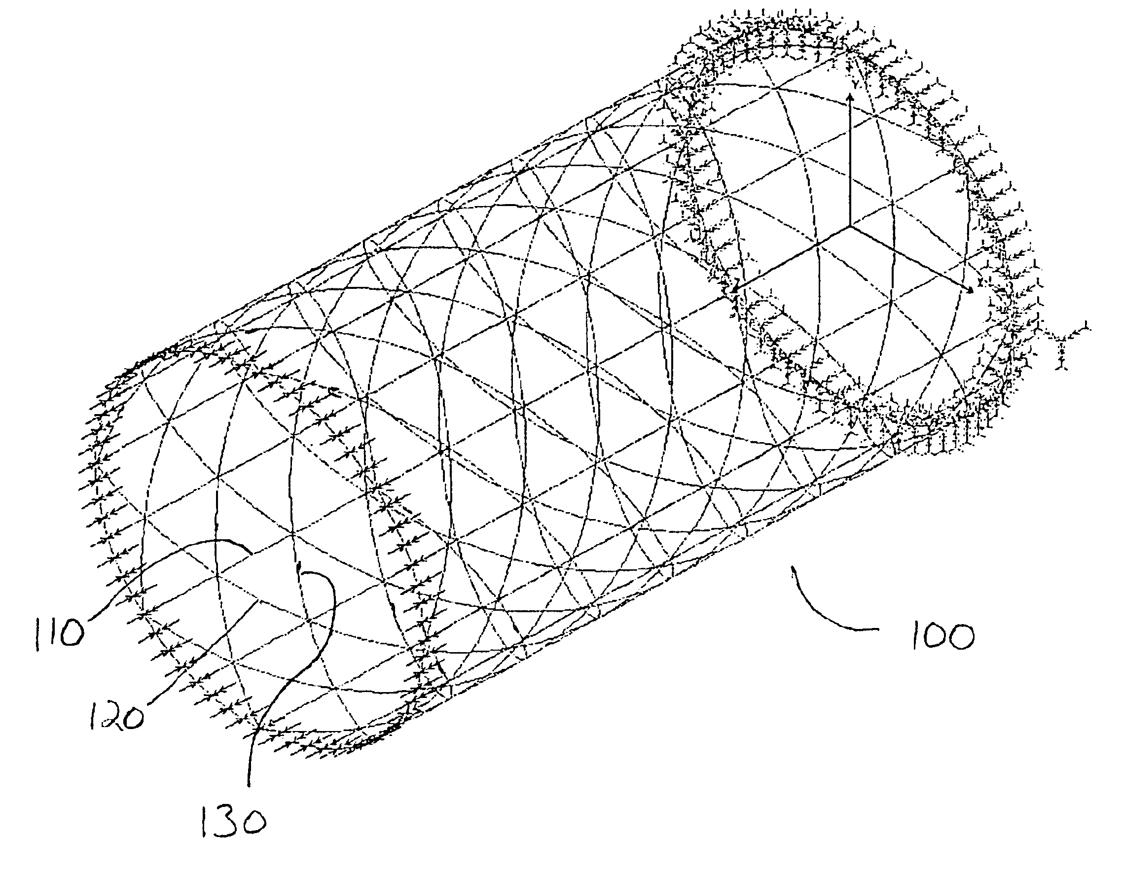
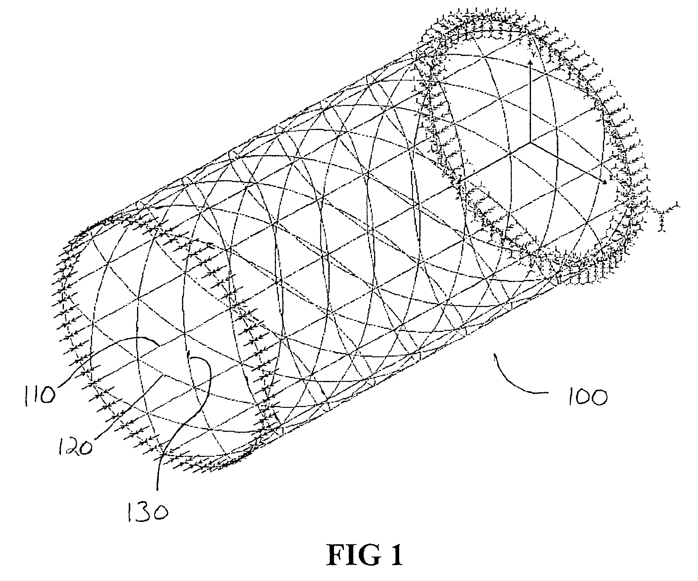
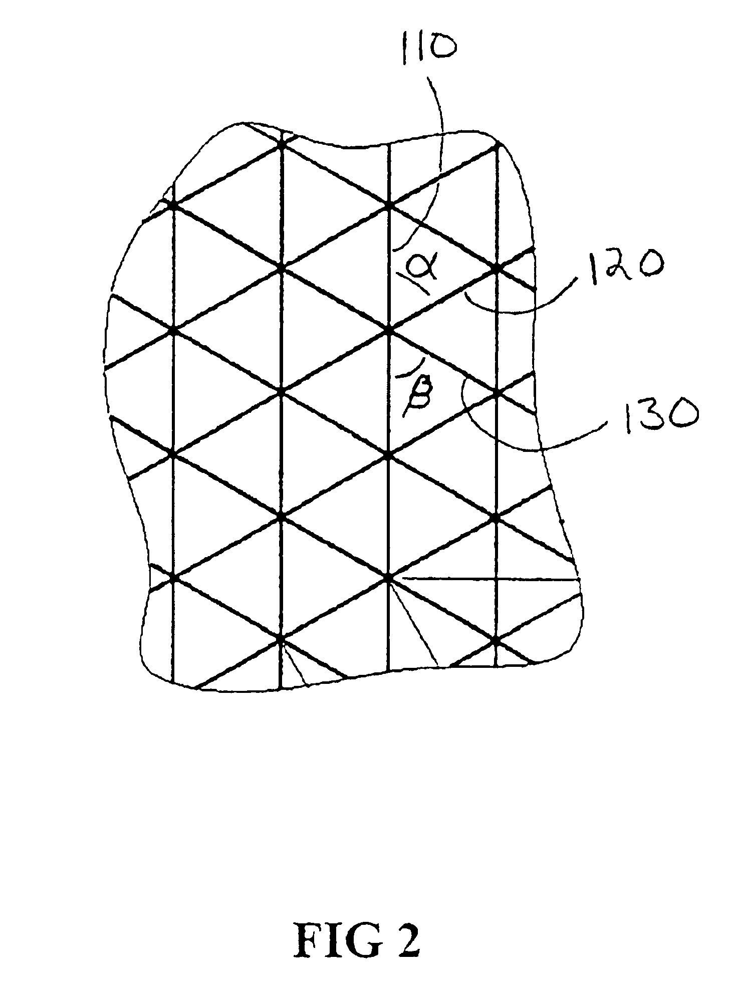
[0021]The preferred embodiment of the invention is a result of the need for a load carrying structure that is capable of being packaged into a reasonably small volume and can be deployed on command, to regain its original shape. Since the matrix can be softened for packaging, the boom is foldable around a very small radius without damage to achieve a bend ratio (fold radius to material thickness) of less than 3. The deployed volume to packed volume ratio achieved by this methodology of material selection, manufacturing and packing is 28 or higher indicating a high packing efficiency. The boom is a cylindrical, isogrid structure that has quasi-isotropic properties. It is a composite system, which is composed of a high modulus fiber / resin that can be folded and stored for a considerable length of time and when required, is deployed via a simple inflation system to form a rigid structure. The boom may then be rigidized by providing heat energy, exposure to the chemical constituents of ...


PUM


Abstract

A boom structure deployed by inflating the structure to a desired shape and rigidizing the structure via an external influence. The structure frame has a series of frame members which are made of a fibrous material and a resin material. This frame is encased in between a pair of membrane layers, an inner membrane inflatable to move the frame into its desired shape and an outer membrane that allows for folding the structure. Following inflation of the inner layer, an external influence acts on the resin material to solidify it, and render the structure rigid. The external influence may also act on the resin material to soften it when it is already rigid, to allow for collapsing and folding of the structure.

Description

FIELD OF THE INVENTION[0001]The invention relates to truss structures that are inflatable, rigidizable, and deployable adapted for space applications as well as ground applications.BACKGROUND OF THE INVENTION[0002]Truss structures have many applications, such as solar arrays, enclosures, antennas, telescopes, solar sails and other structures in space or supports for bridges, piers, buildings or antennas, whether under water or on land. Metal and rigid composite components with mechanical deployment systems were used in the initial stages of the technology development to manufacture support structures for space applications. These structures were massive and could not be packed efficiently for transport. In space applications, for example, their lack of packing efficiency resulted in increased launch vehicle size and mass, which consequentially led to higher system launch costs.[0003]The inherent disadvantages of rigid element mechanically deployed systems led to the development of s...

Claims


Application Information

Patent Timeline
Patent Type & Authority Patents(United States)
IPC IPC(8): E04H15/20
CPCE04H15/20E04H2015/201H01Q1/1235
Inventor CADOGAN, DAVID P.SCARBOROUGH, STEPHEN E.LIN, JOHN K. H.SAPNA, III, GEORGE H.
Owner ILC DOVER LP
Why Eureka
Try Eureka