
Polarized light converting device and method

a converting device and polarized light technology, applied in the field of visual projection display units, can solve the problems of complex and difficult manufacturing and assembly processes, reduced optical efficiency of projection display units, and substantial increase in costs, so as to improve the degree of purity of polarized light, increase optical efficiency, and reduce cost

Inactive Publication Date: 2005-06-28
SAMSUNG ELECTRONICS CO LTD
View PDF4 Cites 4 Cited by
  • Summary
  • Abstract
  • Description
  • Claims
  • Application Information

AI Technical Summary

Benefits of technology

[0014]Accordingly, it is an object of the present invention to provide an improved polarized light converting device with a simple, less-expensive construction and a simple manufacture and assembling process.
[0017]A polarized light separating film is a thin-film coating for improving the degree of purity of polarized light reflecting a S polarized light wave and transmitting only a P polarized light wave. Also, the thin-film coating is a multi-layered dielectric coating.
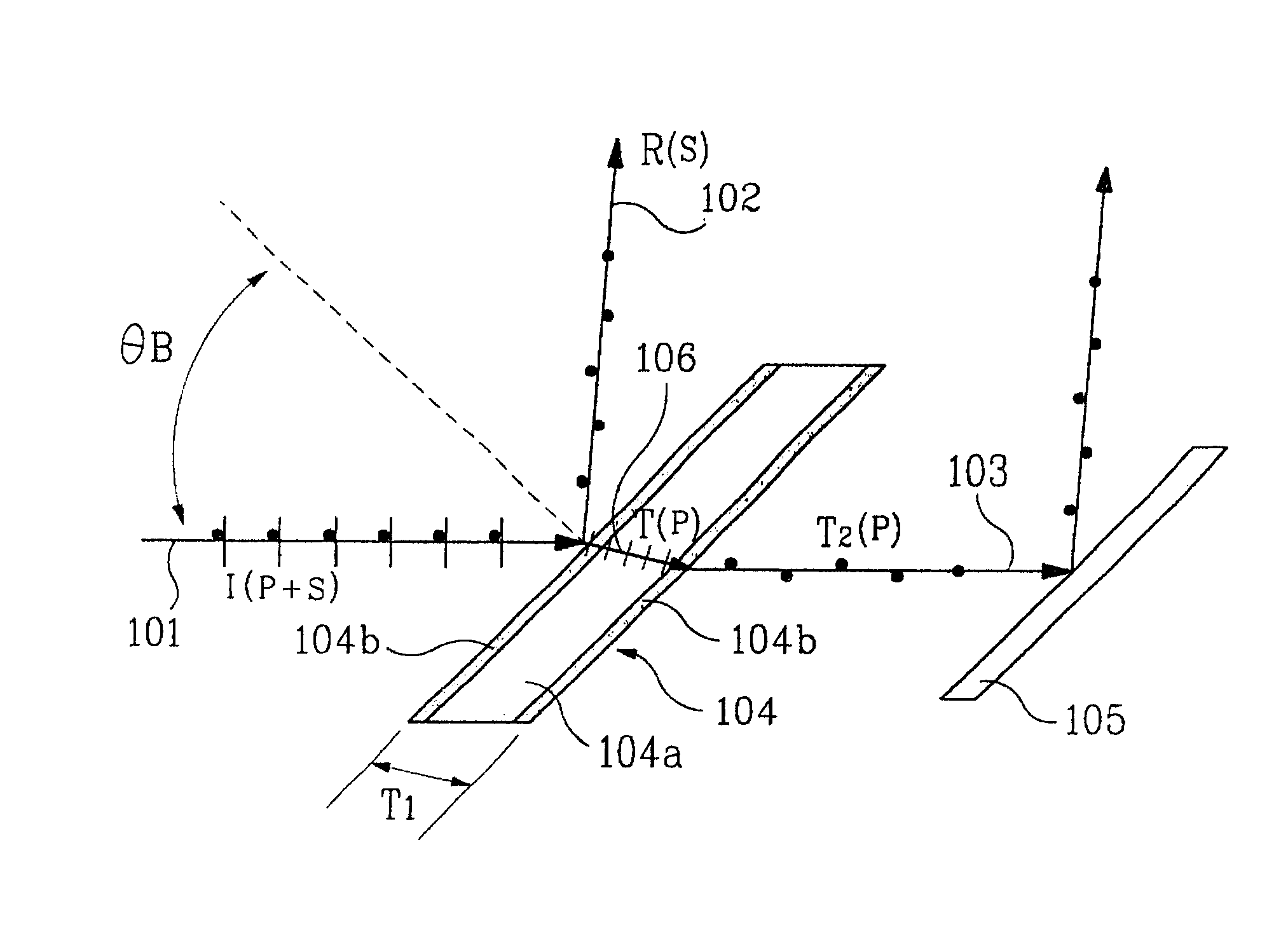
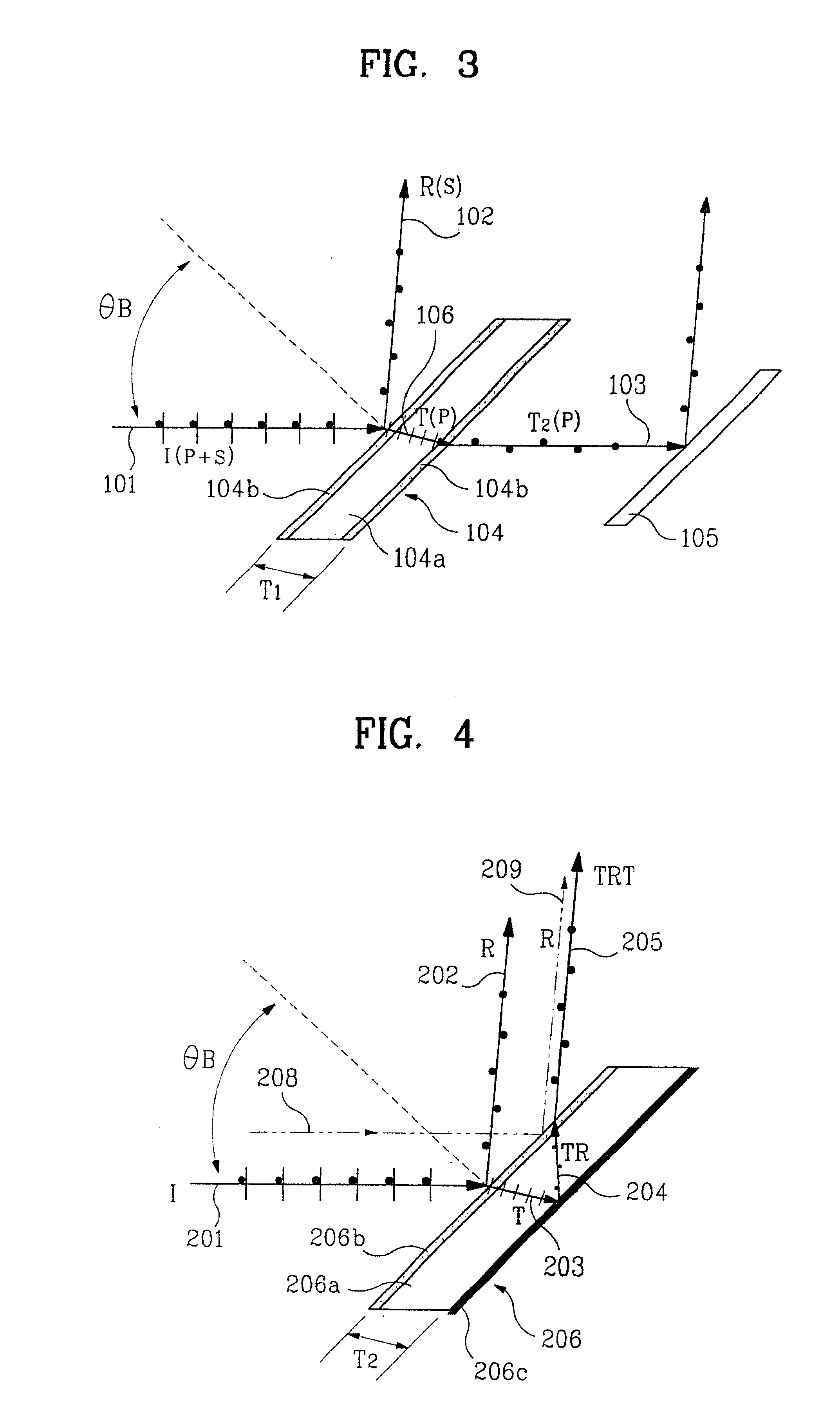
[0018]To achieve the objects of the present invention, another embodiment provides a polarized light converting device for a projection display unit, comprising a medium with predetermined thickness for converting an incident light entering at the Brewster Angle into light having phase difference of λ / 4, a polarized light separating film formed with a thin film coating for increasing the degree of purity which transmits a P polarized light wave and reflects a S polarized light wave from an incident light entering at the Brewster Angle by a coated front side of the medium, and a full reflecting mirror reflecting a light transmitted through the medium by a coated back side of the medium. Thus, from an incident light entering at the Brewster Angle, a S polarized light wave is reflected and a P polarized light wave is transmitted on a coating surface of a polarized light separating film. The transmitted P polarized light wave has a phase difference of λ / 4 when transmitted through a medium of predetermined thickness and has a phase difference of λ / 4 when transmitted through the medium after being reflected on the reflecting mirror. Consequently, it has a phase difference of λ / 2 (i.e., λ / 4+λ / 4=λ / 2), and proceeds in same direction as a S polarized light wave reflected on the polarized light separating film.
[0020]A polarized light separating film is a thin film coating for improving the degree of purity of polarized light reflecting a S polarized light wave and transmitting only a P polarized light wave from an incident light. Also, the thin film coating is a multi-layered dielectric coating.
[0021]Therefore, the present invention has the advantage of increasing optical efficiency while lowering the cost. This is accomplished by using a medium which simultaneously performs separation and conversion of polarized light.

Problems solved by technology

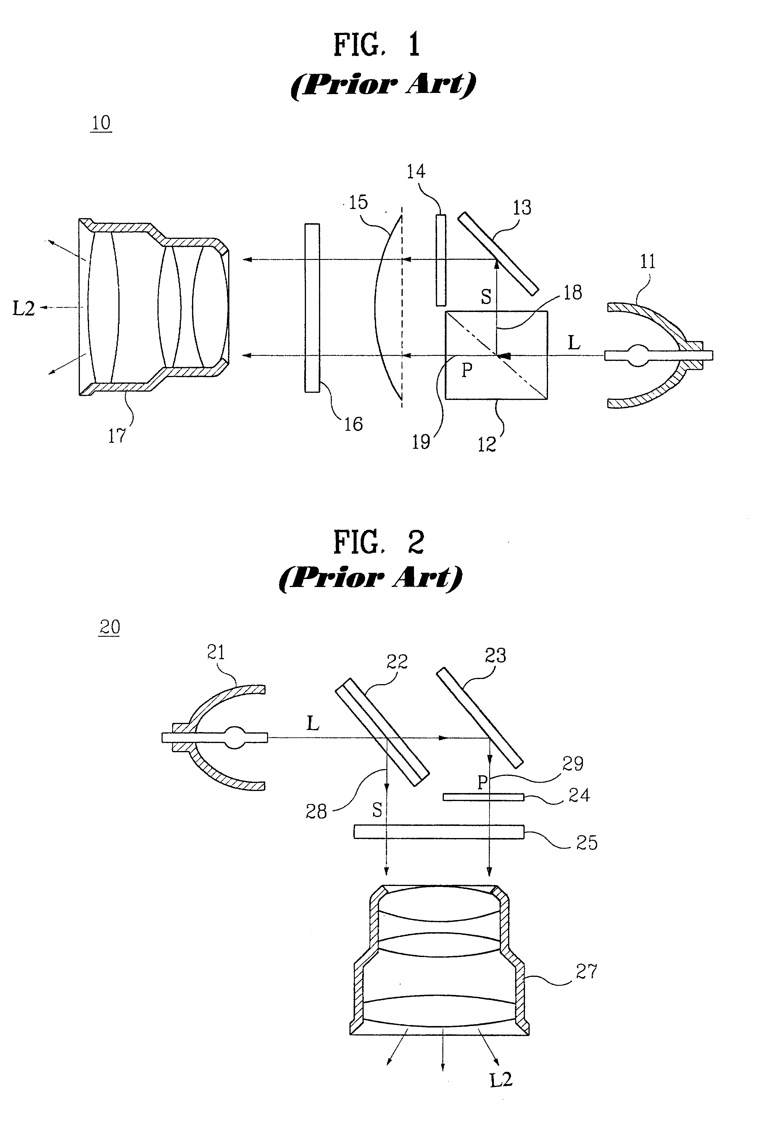
However, in each instance, the projection display unit is subject to a decrease of 50% in optical efficiency; also using an expensive polarized light converter causes a substantial increase in cost.
Further, since a small polarized light separator and a polarized light converter are connected and used at a right angle to the light direction, in order to ensure spatial uniformity of intensity of light, the necessary manufacture and assembling processes are complex and difficult.

Method used


Image

  • Polarized light converting device and method
  • Polarized light converting device and method
  • Polarized light converting device and method

Examples


Embodiment Construction

[0027]Referring to FIG. 3, a cross-sectional view showing a polarized light converting device 104 of a projection display unit according to the present invention is seen. Device 104 is a projection display unit which comprises a medium 104a with a predetermined thickness and a polarized light-separating film 104b, coating the front and back sides of the medium. Medium 104a is made of a material having a short light axis and a double refraction, the ordinary refractive index of which is different from an extraordinary refractive index for visible rays (wavelength of 400-700 nm). As will appear, device 104 is an integrally-formed PBS and delay device (PBSDD) comprising integrally-formed means for separating the incident light beam into a reflected S component and a transmitted P component, and also for changing the direction of the P component in such manner that it is parallel to, and in the same direction as, the S component. (As used hereinafter, the term “integrally formed” refers...


PUM

PropertyMeasurementUnit
refractive indexaaaaaaaaaa

Abstract

An integrally-formed polarized light converting device of a projection display unit comprises a medium of a predetermined thickness converting incident light entering at the Brewster Angle into light having a phase difference of λ / 2 and a polarized light separating film reflecting a S polarized light wave and transmitting a P polarized light wave from the incident light entering at the Brewster Angle by a coated front side and a coated back side of said medium. A polarized light separating film having a coated front side reflects the S polarized light wave and transmits the P polarized light wave from the incident light entering at the Brewster Angle. The transmitted P polarized light wave has a phase difference of λ / 2 when transmitted through a medium of predetermined thickness and proceeds in the same direction as the S polarized light wave reflected by the polarized light separating film.

Description

CLAIM OF PRIORITY[0001]This application makes reference to, incorporates the same herein, and claims all benefits accruing under 35 U.S.C. §119 from the inventor's application POLARIZATION SEPARATING AND CONVERTING GLASS OF PROJECTION DISPLAY UNIT filed with the Korean Industrial Property Office on 21 Jul. 1999 and there duly assigned Serial No. 29639 / 1999.BACKGROUND OF THE INVENTION[0002]1. Field of the Invention[0003]The present invention relates to a visual projection display unit, and more particularly to a polarized light converting device in which a polarized light separator and a polarized light converter are integrated to increase optical efficiency.[0004]2. Description of the Prior Art[0005]A visual projection system such as a projection television and a video projector produce images from a visual display means. The latter may be a specially manufactured small cathode-ray tube (CRT), liquid crystal display (LCD) device, or polymer dispersion liquid crystal display (PDLCD) ...

Claims


Application Information

Patent Timeline
Patent Type & Authority Patents(United States)
IPC IPC(8): G02B27/28G02F1/13G02F1/1335G03B21/14H04N5/74G02B5/30
CPCG02B27/286H04N9/315H04N5/7408H04N5/74G02F1/1335
Inventor LEE
Owner SAMSUNG ELECTRONICS CO LTD
Learn More