Optical fiber alignment device and method

Inactive Publication Date: 2005-06-28
AVAGO TECH INT SALES PTE LTD
View PDF12 Cites 6 Cited by
  • Summary
  • Abstract
  • Description
  • Claims
  • Application Information

AI Technical Summary

Benefits of technology

[0007]an adjustment means located at a distance from the universal joint such that displacement of the adjustment means causes a pivotal movement of the fiber about a pivotal point of the universal joint and results in a smaller displacement of the end of the optical fiber.
[0008]To aid hermetic sealing for high reliability, in one embodiment the universal joint comprises a flexible material between the optical fiber and a mount.

Problems solved by technology

Coupling efficiency between an optical fiber and a laser diode is limited by the accuracy and stability of the alignment achievable during the assembly process.
However, this simple technique is limited in precision by the manufactured accuracy of the silicon and the fiber and subsequent movement due to thermal stresses during the joining process.
However, this technique suffers from the disadvantage of creep or flow of the deformed material and is therefore not stable in the long term.
Furthermore, the problem of creep is increased due to the high temperature to which such coupling assemblies are likely to be subjected.
Such creep reduces the coupling efficiency between the laser and the fiber as the assembly ages.
However, as the fiber tip is so close to the output facet of the laser this means that a small displacement from the optimum position causes a significant drop in coupling efficiency.
At distances further from the output facet of the laser, displacements from the optimum position do not have such a great effect but coupling efficiency is reduced.

Method used


Image

  • Optical fiber alignment device and method
  • Optical fiber alignment device and method
  • Optical fiber alignment device and method

Examples


Embodiment Construction

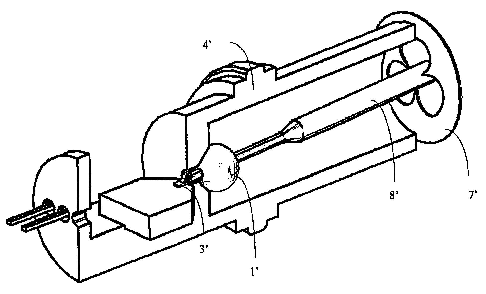
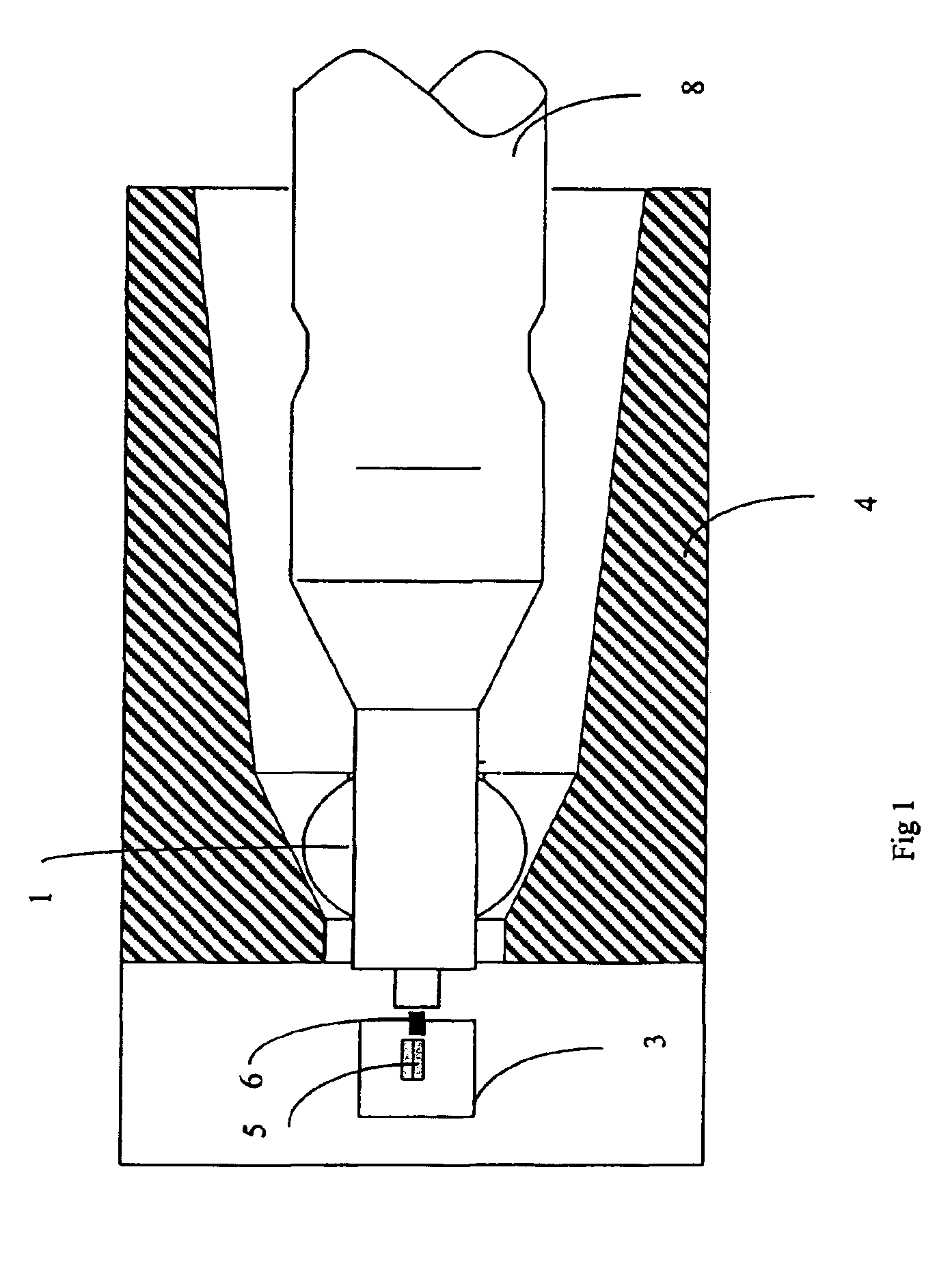
[0028]Referring now to FIG. 1 a laser diode 5 is mounted on a thermally conductive bench 3. The bench is fabricated from a material with a low thermal expansion coefficient such as Kovar, a nickel cobalt iron alloy. Other materials that work well include copper tungsten alloys which are materials which combine the conductivity of copper, thus providing heat spreading, with the low expansion coefficient of tungsten. Other suitable materials may be used for fabrication of the bench 3. It is possible to calculate limits for the thermal expansion of the chosen material, and to compensate for such expansion when designing the assembly.

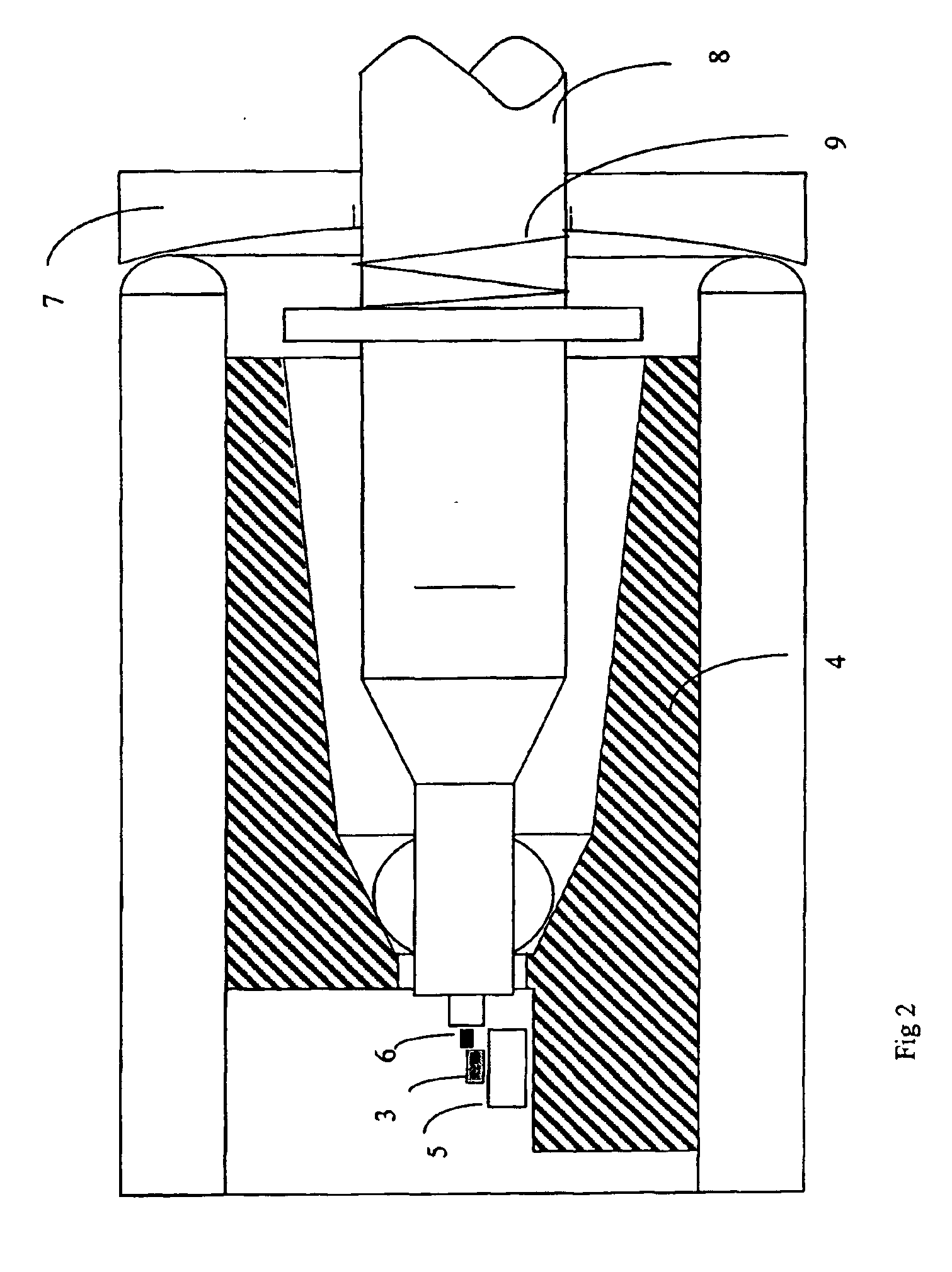
[0029]The bench 3 and an optical fiber 6, which is mounted in a stainless steel tube 8, are co-located in a mount 4. The optical fiber is inserted centrally in the stainless steel tube. Any misalignment of the optical fiber 6 with the centre of the tube 8 is compensated for during a passive alignment procedure, which is described later.

[0030]The laser diode...


PUM


Abstract

A device and method for alignment of an optical fiber with an output facet of a laser diode that are to be co-located on a mount, to obtain a substantially optimum coupling efficiency. The device is particularly applicable to assemblies to be used in a submarine.

Description

FIELD OF THE INVENTION[0001]This invention relates to a device and method for aligning an optical fiber with the output facet of a laser diode.DISCUSSION OF THE BACKGROUND ART[0002]Coupling efficiency between an optical fiber and a laser diode is limited by the accuracy and stability of the alignment achievable during the assembly process. Alignment of an optical fiber and a laser diode may be achieved by placing the optical fiber using a feature which has been etched onto a silicon ‘optical bench’, upon which the laser diode has already been precisely attached. However, this simple technique is limited in precision by the manufactured accuracy of the silicon and the fiber and subsequent movement due to thermal stresses during the joining process. Another technique uses a mount to support the optical fiber. Once the laser and the optical fiber have been aligned and attached to the bench, the mount is mechanically deformed until an optimum coupling efficiency is achieved. However, th...

Claims


Application Information

Patent Timeline
IPC IPC(8): G02B6/42
CPCG02B6/4237G02B6/4226G02B6/4224
Inventor AMORIM, GONCALO AGRA
Owner AVAGO TECH INT SALES PTE LTD
Why Eureka
Try Eureka