Catalyst for purifying exhaust gas

a technology of catalyst and exhaust gas, which is applied in the field of catalyst, can solve the problems of many problems that must be solved in the apparatus, the filter may suffer from cracks, and the apparatus may be complicated in terms of the system, so as to achieve the effect of efficient purification of not only co and h

Inactive Publication Date: 2005-06-28
CATALER CORP
View PDF21 Cites 46 Cited by
  • Summary
  • Abstract
  • Description
  • Claims
  • Application Information

AI Technical Summary

Benefits of technology

[0014]The present invention has been developed in view of the aforementioned circumstances. It is therefore an object of the present invention to make it possible to efficiently purify not only CO and HC, which are contained in an exhaust gas, being emitted from a DE, but also SOF and particulate materials, which are composed of sulfates, and the like.
[0021]In accordance with the present exhaust gas purifying catalysts, it is possible to efficiently purify not only CO and HC, which are contained in an exhaust gas, being emitted from a DE, but also SOF and particulate materials, which are composed of sulfates, and the like.

Problems solved by technology

However, concerning DE's, the regulations and the developments of the techniques are behind those of the gasoline engines because of the singular circumstance that the harmful components are mainly emitted as particulate materials.
However, there remain many problems to be solved in the apparatus, to which a method using a filter is applied, when the apparatus is put into actual applications.
For instance, the apparatus requires a recycling apparatus for burning the captured particulate materials; when the captured particulate materials are burned, the filter may suffer from cracks in recycling; the filter might be clogged up by ashes; the apparatus might be complicated in terms the system, and so on.
The open type SOF decomposition catalyst has a drawback in that it exhibits a low reduction efficiency to dry soot.
However, an open type SOF decomposition catalyst has a disadvantage in that the activities of the catalytic ingredient might be so low under a low temperature condition that the conversion of SOF lowers, though it can efficiently decompose SOF under an elevated temperature condition.
Then, a drawback might arise in that the catalyst is clogged up by the deposited soot so that the catalytic performance degrades.
Moreover, in an open type SOF decomposition catalyst, there might be a problem in that even SO2, which is contained in an exhaust gas, is oxidized to generate SO3 and SO4 in a high temperature region, and that the resulting SO3 and SO4 are turned into sulfates so that the emission of particulate materials increases inversely.
In addition, in an open type SOF decomposition catalyst, it has been known that the catalytic ingredient is subjected to poisoning by sulfur, which is contained in exhaust gases, being emitted from DE's, in a large amount, so that the catalytic activities of the catalytic ingredient lower.
Thus, the catalytic activities degrade, because the resulting aluminum sulfate covers the catalytic ingredient.
However, such a catalyst does not exhibit an adsorption ability to SOF, and accordingly allows to emit HC as well as SOF as they are in a low temperature region.
However, even the above-described catalytic apparatus for purifying an exhaust gas, which is emitted from a DE, is not satisfactory in terms of the purifying performance of SOF as well as the sulfur poisoning resistance.

Method used


Image

  • Catalyst for purifying exhaust gas
  • Catalyst for purifying exhaust gas

Examples


example no.1

EXAMPLE No. 1

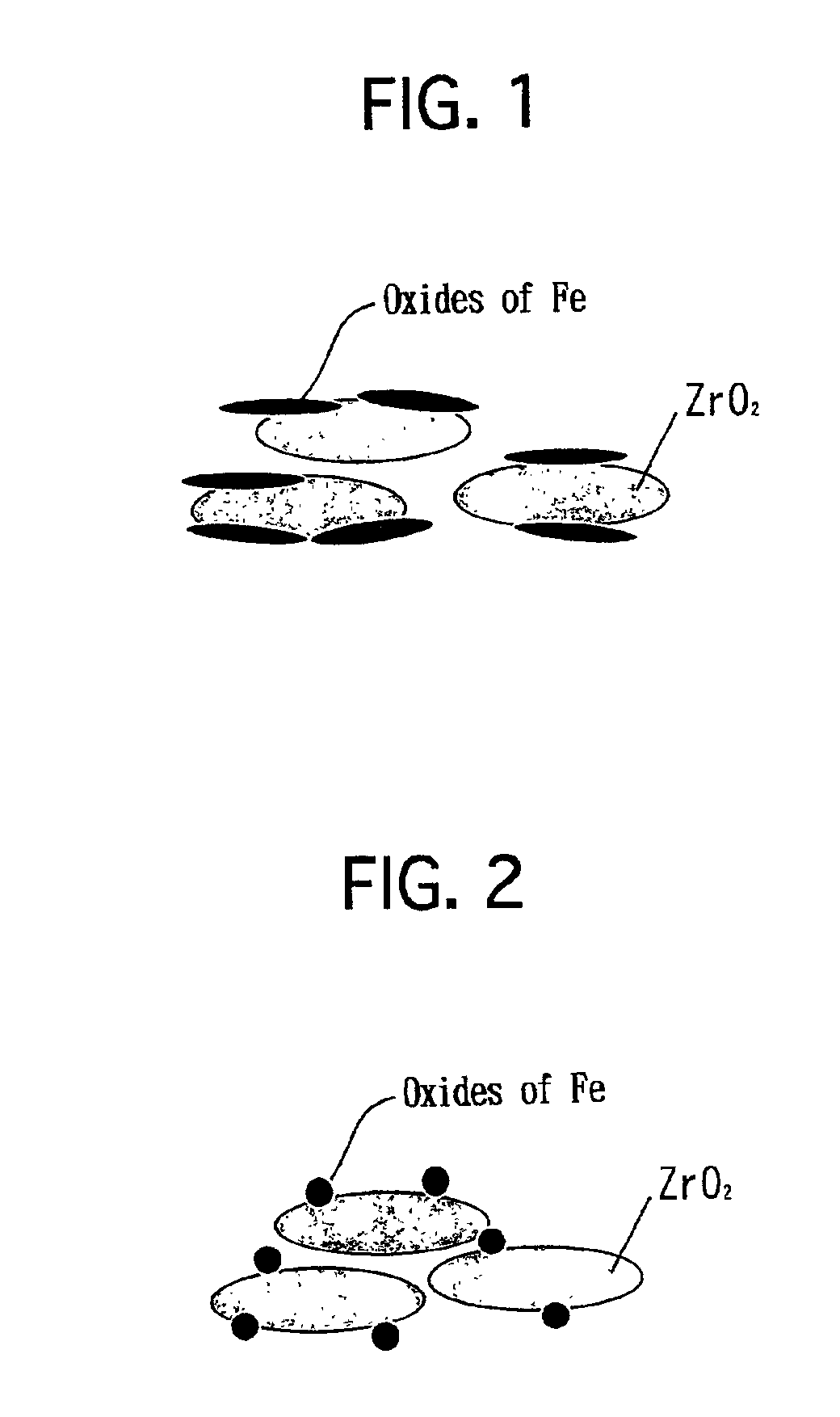
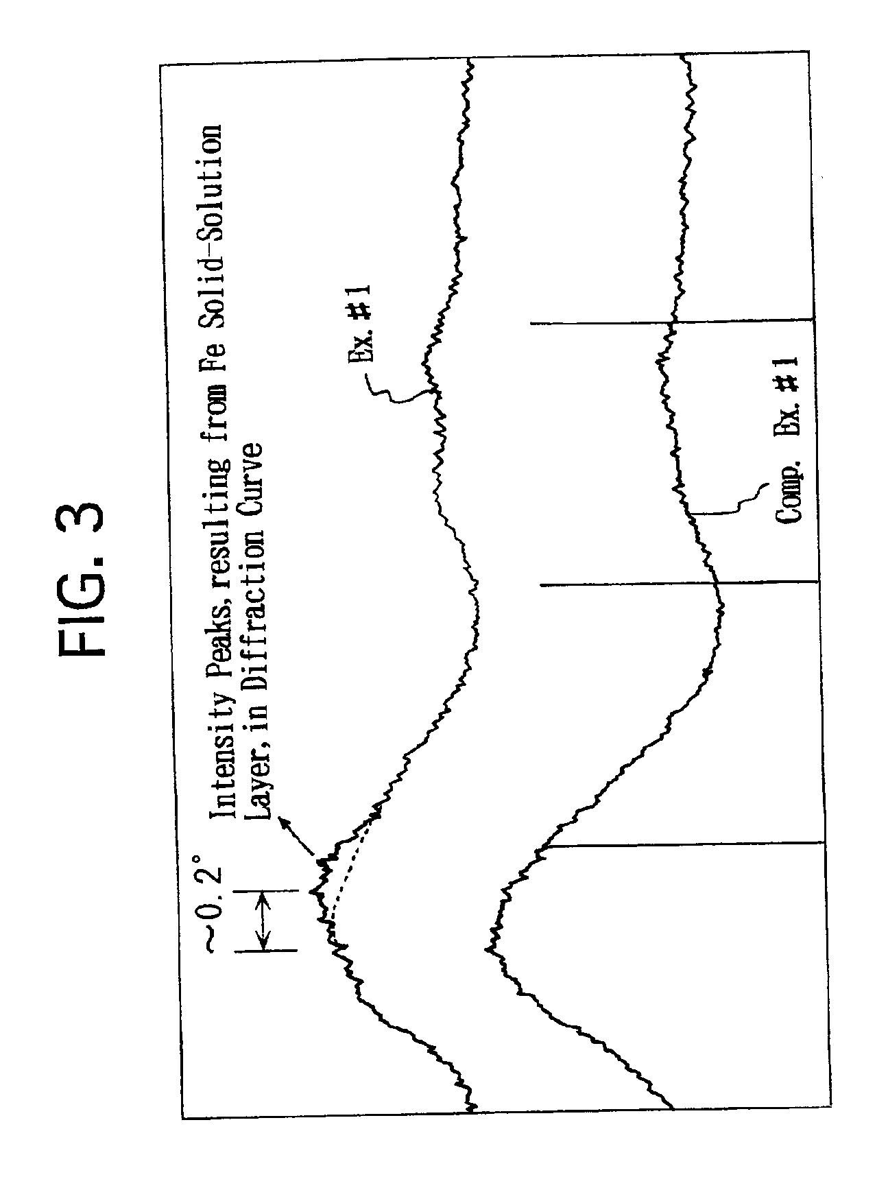
[0043]A neodymium nitrate (Nd(NO3)3) aqueous solution was impregnated into a commercially available zirconia powder to load Nd thereon. Note that the zirconia powder exhibited a BET specific surface area of 100 m2 / g. The zirconia powder was dried at 150° C. for 1 hour. Thereafter, the zirconia powder was calcined at 800° C. in air for 2 hours. Thus, a heat-resistant zirconia powder was prepared. Note that the heat-resistant zirconia powder included Nd in an amount of 20 atomic % with respect to Zr. As set forth in Table 1 below, the heat-resistant zirconia powder exhibited a BET specific surface area of 69 m2 / g. According to the results of an X-ray diffraction analysis, it was verified that a part of Nd was solved into ZrO2.

[0044]Subsequently, 800 g of the resulting heat-resistant zirconia powder was mixed into 135 g of an iron nitrate (Fe(NO3)3.9H2O) aqueous solution. While fully stirring the mixture, the mixture was evaporated to dry at 120° C. The dried solid was pul...

example no.2

EXAMPLE No. 2

[0047]A cerium nitrate (Ce(NO3)3) aqueous solution was impregnated into a commercially available zirconia powder to load Ce thereon. Note that the zirconia powder exhibited a BET specific surface area of 100 m2 / g. The zirconia powder was dried at 150° C. for 1 hour. Thereafter, the zirconia powder was calcined at 800° C. in air for 2 hours. Thus, a heat-resistant zirconia powder was prepared. Note that the heat-resistant powder included Ce in an amount of 30 atomic % with respect to Zr. As set forth in Table 1 below, the heat-resistant zirconia powder exhibited a BET specific surface area of 57 m2 / g. According to the results of an X-ray diffraction analysis, it was verified that a part of Ce was solved into ZrO2.

[0048]Except that the heat-resistant zirconia powder with Ce added was used instead of the heat-resistant zirconia powder with Nd added, an exhaust gas purifying catalyst of Example No. 2 was prepared in the same manner as Example No. 1.

example no.3

EXAMPLE No. 3

[0049]Except that a commercially available zirconia powder was used instead of the heat-resistant zirconia powder with Nd added, an exhaust gas purifying catalyst of Example No. 3 was prepared in the same manner as Example No. 1. Note that the zirconia powder exhibited a BET specific surface area of 100 m2 / g.


PUM

PropertyMeasurementUnit
BET specific surface areaaaaaaaaaaa
temperatureaaaaaaaaaa
BET specific surface areaaaaaaaaaaa

Abstract

A catalyst for purifying an exhaust gas includes zirconia particles, and a transition metal layer, covering at least a part of a surface of the zirconia particles in a lamellar manner. It can reduce the emission of particulate materials (i.e., P.M.), such as SOF and sulfates, because the contacting area enlarges between the transition metal layer and materials to be purified.

Description

BACKGROUND OF THE INVENTION[0001]1. Field of the Invention[0002]The present invention relates to a catalyst, which can efficiently purify soluble organic fractions (i.e., SOF) and soot-like components in an exhaust gas, being emitted from a diesel engine (hereinafter abbreviated to “DE ”), and which can reduce the emission of particulate materials.[0003]2. Description of Related Art[0004]Concerning gasoline engines, the harmful materials in the exhaust gases, which are emitted therefrom, have been reduced steadily because of the severe regulations on the exhaust gases and the developments of the techniques for coping with the regulations. However, concerning DE's, the regulations and the developments of the techniques are behind those of the gasoline engines because of the singular circumstance that the harmful components are mainly emitted as particulate materials. Accordingly, it has been desired to develop an exhaust gas purifying catalyst, which can securely purify the harmful c...

Claims


Application Information

Patent Timeline
Patent Type & Authority Patents(United States)
IPC IPC(8): B01D53/94B01J23/10B01J23/83B01J23/76B01J29/00B01J29/06F01N3/10B01J29/46B01J37/02
CPCB01D53/94B01D53/944B01J23/83B01J29/06B01J23/10B01J2229/40
Inventor KIMURA, MAREOHASEGAWA, YORIKOAONO, NORIHIKOTANAKA, SEIJI
Owner CATALER CORP
Why Eureka
Try Eureka