Ring architecture for an optical satellite communication network with passive optical routing

a satellite communication network and optical satellite technology, applied in the field of space and communications satellites, can solve the problems of increasing the scarce remaining slots, consuming a significant amount of electric power for high-speed switching electronics, and limited growth to higher frequencies, so as to reduce power consumption and weight, and increase network capacity

Inactive Publication Date: 2005-06-28
HUGHES ELECTRONICS
View PDF32 Cites 76 Cited by
  • Summary
  • Abstract
  • Description
  • Claims
  • Application Information

AI Technical Summary

Benefits of technology

[0012]In the preferred embodiment, each pair of communicating satellites use different optical carriers (i.e., optical signals of different wavelength and / or polarization) for communicating between each other. The optical carriers are assigned in such a way that only substantially different carriers are present simultaneously on each direct satellite-to-satellite optical link. Upon receiving an optical beam from a neighbor, each satellite uses an optical drop to separate optical carriers designated for down transmission from this satellite from the other carriers. The remaining carriers are amplified optically and relayed to the next satellite along the ring without being converted into electronic format. Since electronics is not involved into routing of the relayed traffic, significant load is removed from the on-board electronics, resulting in a reduced power consumption and weight as well as in increased network capacity.

Problems solved by technology

As a result, the government has been auctioning the increasingly scarce remaining slots.
Growth to higher frequencies is limited by difficult problems in technology and propagation.
High speed switching electronics consume a significant amount of electric power which is always at a premium on board of satellites.
Moreover, as the volume of data traffic transmitted by numerous RF and optical channels of a satellite increases, the electronic switch becomes the bottleneck that limits the overall network capacity.

Method used


Image

  • Ring architecture for an optical satellite communication network with passive optical routing
  • Ring architecture for an optical satellite communication network with passive optical routing

Examples


Embodiment Construction

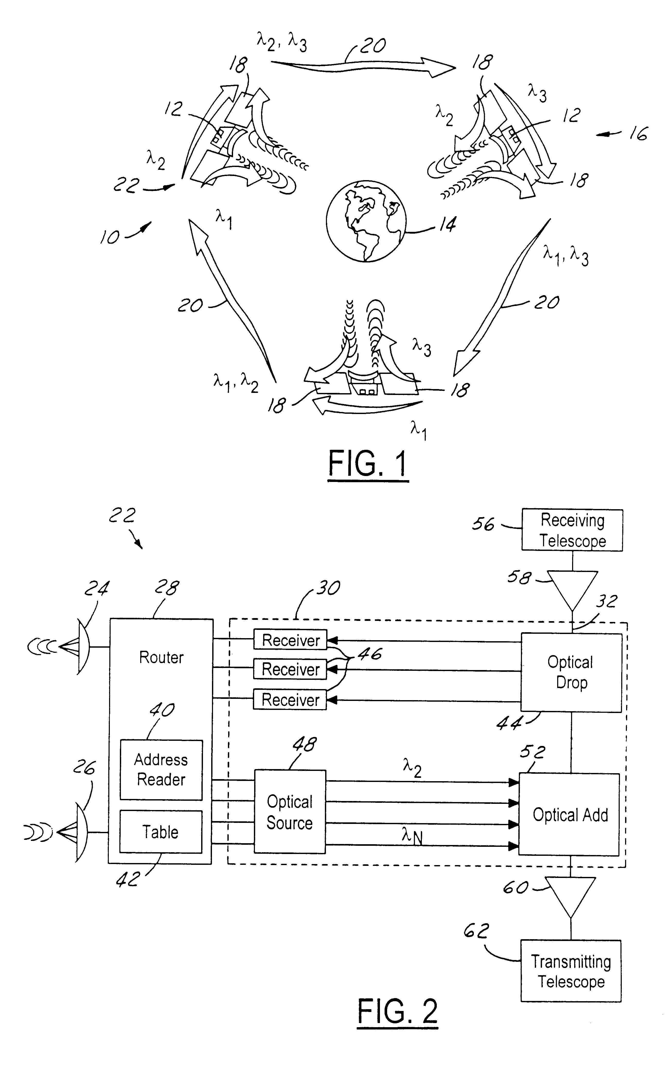
[0016]Referring now to FIG. 1, a communication system 10 is comprised of a plurality of satellites 12 orbiting the earth. Satellites 12 may be in geosynchronous orbit (GSO), medium earth orbit (MEO) and low earth orbit (LEO) around earth 14. Although this invention may be used for other types of orbits, this invention is particularly suitable for satellites in GSO.

[0017]Satellites 12 form a network 16. Each satellite 12 receives and transmits radio frequency (RF) communications to earth by way of antennas 18. As will be further described below, each satellite 12 communicates with an adjacent satellite in network 16 using optical signals. Because the satellites are spaced apart with respect to the earth and, if satellites 12 are in LEO or MEO, the relative position of satellites 12 with respect to the earth is changing. At any particular time, one or more satellites may be in view of the earth at a suitable elevation angle. As will be further described below, communications desired f...


PUM


Abstract

A node for satellite system communications between a ground station and a satellite includes a fiber optic bus on the satellite. An optical drop is coupled to the bus. The optical drop resolves an optical signal destined to the given satellite from the optical bus. An uplink and downlink receive and transmit communications from a ground terminal. A router is coupled to the optical drop and the uplink and downlink. An address reader and a table are used by the router to determine the destination of the received RF signals. The received RF signals are converted to optical signals by an optical source. The optical source has a wavelength that corresponds with the destination satellite. The optical signals are transmitted to an adjacent satellite by an optical transmitter such as a transmitting telescope.

Description

TECHNICAL FIELD[0001]The present invention relates to space and communications satellites, and more particularly, to a communication system to interconnect satellites.BACKGROUND ART[0002]Satellites in geostationary orbits (GSO's) have been widely preferred because of the economic advantages afforded by such orbits. In a geostationary orbit, a satellite traveling above the earth's equator, in the same direction as that in which the earth is rotating, and at the same angular velocity, appears stationary relative to a point on the earth. These satellites are always “in view” at all locations within their service areas, so their utilization efficiency is effectively one-hundred percent. Antennas on earth need be aimed at a GSO satellite only once; no tracking system is required.[0003]Coordination between GSOs and with terrestrial services is facilitated by governmental allocation of designated “slots” angularly spaced according to service type.[0004]Given the desirability of geostationa...

Claims


Application Information

Patent Timeline
Patent Type & Authority Patents(United States)
IPC IPC(8): H04B10/00H04B10/118
CPCH04B10/118
Inventor IONOV, STANISLAV I.VALLEY, GEORGE C.
Owner HUGHES ELECTRONICS
Why Eureka
Try Eureka