
Automatic router configuration

a router and configuration technology, applied in the direction of electrical equipment, digital transmission, data switching networks, etc., can solve the problems of typical configuration of network topology with a lot of effort and complexity, and achieve the effect of flexible installation and improved performan

Inactive Publication Date: 2005-06-28
SONUS NETWORKS
View PDF8 Cites 65 Cited by
  • Summary
  • Abstract
  • Description
  • Claims
  • Application Information

AI Technical Summary

Benefits of technology

[0003]Invention resides in simplified and automated approach to network configuration using improved multi-layer switching apparatus and methodology. In particular, packet flows or signals are learned or “snooped” while passing through improved multi-layer switch, and representations of fast routes are loaded into forwarding table including Layer-2 and / or Layer-3 addressing information in digital storage, such as content-addressable memory (CAM), on flow-by-flow or route-by-route basis. Preferred approach improves performance by avoiding pre-determination of network topology. Improved multi-layer switch is preferably installed flexibly (i.e., plug-and-play), essentially without configuring network or improved multi-layer switch. Such multi-layer switch offloads significant portion of traffic load from routers, thereby freeing routers for other use.

Problems solved by technology

In conventional network systems, substantial and complex effort is required typically to configure network topology for switching and routing equipment.

Method used


Image

  • Automatic router configuration
  • Automatic router configuration
  • Automatic router configuration

Examples


Embodiment Construction

)

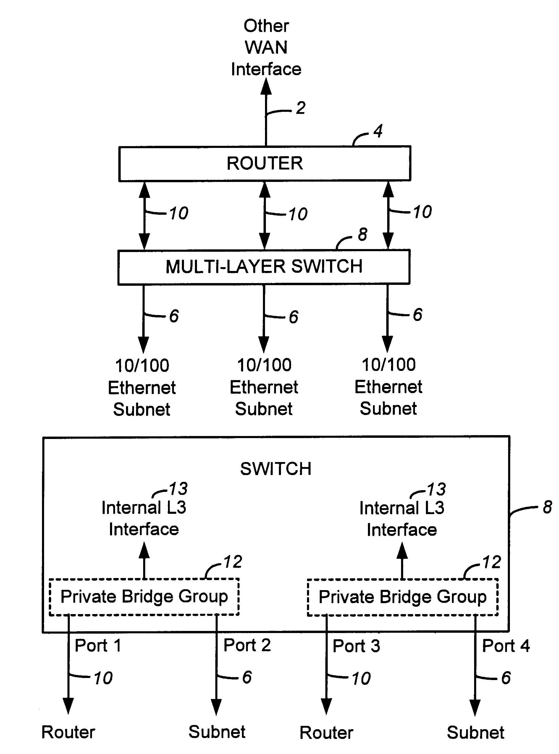
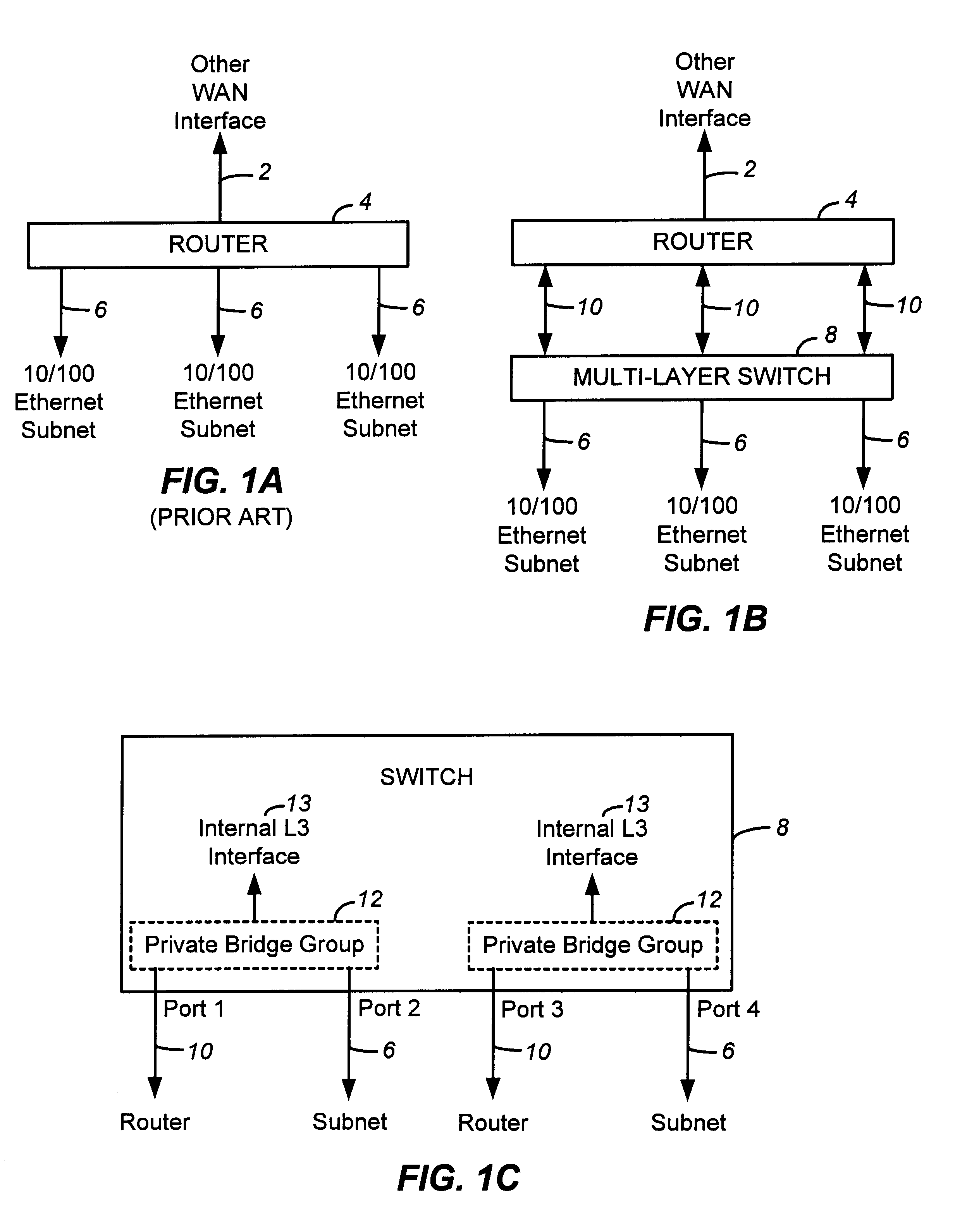
[0005]In FIG. 1A, block diagram of conventional (PRIOR ART) network router 4, such as commercial network routing equipment available from Cisco, couples wide-area network (WAN) interface 2 to one or more 10 / 100 Ethernet subnet local-area network (LAN) 6. Ordinarily, packets are routed by router 4 to and from various source and destination network nodes coupled thereto.

[0006]In accordance with preferred embodiment of present invention claimed herein, conventional network router system is modified, as shown in FIG. 1B, to include improved multi-layer switching circuit and associated software functionality 8 coupled 10 thereto. As coupled, improved multi-layer switch 8 serves effectively to “front-end” conventional router 4, thereby offloading substantial portion of traffic handled by router 4, extending useful life expectancy of router 4, and improving overall network performance. In particular, simplified and automated network configuration is achieved whereby packet flows are ident...


PUM


Abstract

Network router and multi-layer switch configuration is simplified, whereby packet flows are intercepted and identified while passing through, and fast routes are learned and cached on flow-by-flow basis. Simplified approach avoids configuration of network topology and provides plug-and-play installation, without configuring network or improved multi-layer switch.

Description

FIELD OF INVENTION[0001]Invention relates to digital networking apparatus and methodology, and more particularly to automatic router configuration approach for improving network switching performance and flexibility.BACKGROUND OF INVENTION[0002]In conventional network systems, substantial and complex effort is required typically to configure network topology for switching and routing equipment. More recently, so-called multi-layer switches provide interconnection at Layer 2 and Layer 3 protocol to improve network integration and performance. However, because such multi-layer switches effectively functioning as hardware-based routers, thereby employing conventional routing protocols such as RIP (Routing Information Protocol) or OSPF (Open Shortest Path First) to calculate paths through the network, network managers still must reconfigure ports and reassign subnetwork numbers. Accordingly, there is need for simplified network router configuration.SUMMARY OF INVENTION[0003]Invention re...

Claims


Application Information

Patent Timeline
IPC IPC(8): H04J3/02H04L12/56
CPCH04L45/7453H04L45/02H04L49/602
Inventor SLOANE, TIMON
Owner SONUS NETWORKS
Learn More