
Signal processor for correcting and detecting errors

a signal processor and error detection technology, applied in the field of signal processors, can solve the problems of high error rate the signal processor cannot perform high-speed access and higher-speed data processing, and the error rate is higher in the dvd-rom data than in the cd-rom data, so as to achieve high-speed data transmission and reduce the time required for memory access to the memory means

Inactive Publication Date: 2005-06-28
PANASONIC CORP
View PDF17 Cites 68 Cited by
  • Summary
  • Abstract
  • Description
  • Claims
  • Application Information

AI Technical Summary

Benefits of technology

[0021]In the signal processor so constructed, the number of data error corrections can be reduced, whereby reduced power consumption of the device itself can be achieved. Further, since the number of memory accesses to the memory means for error correction can be reduced, the access right to the memory means can be assigned to another block, whereby high-speed processing of the signal processor is realized.
[0023]In the signal processor so constructed, the time required for memory access to the memory means can be reduced by reducing the number of error corrections and, furthermore, speedup of data processing is achieved.
[0025]In the signal processor so constructed, based on the result of error detection, when there is no error, the data is transmitted to the host computer without performing error correction again, whereby the number of error corrections can be reduced. Accordingly, the power consumption of the device itself can be reduced.
[0027]In the signal processor so constructed, the time required for memory access to the memory means can be reduced by terminating the second and more error corrections or reducing the number of error corrections for the data in each predetermined error correction block stored in the memory means, and further high-speed transmission of the data to the host computer is achieved.

Problems solved by technology

In the case of DVD-ROM data, however, since inputted data is not previously subjected to error correction in contrast to the CD-ROM data, the error rate is higher in the DVD-ROM data than in the CD-ROM data.
Therefore, when the DVD-ROM data is subjected to CRC, the result of CRC is, in most cases, that there are errors in the DVD-ROM data.
That is, since reading and writing of data are performed frequently through the buffer memory 64, the memory band width is pressed and, therefore, the signal processor cannot perform high-speed access and higher-speed data processing.

Method used


Image

  • Signal processor for correcting and detecting errors
  • Signal processor for correcting and detecting errors
  • Signal processor for correcting and detecting errors

Examples


embodiment 1

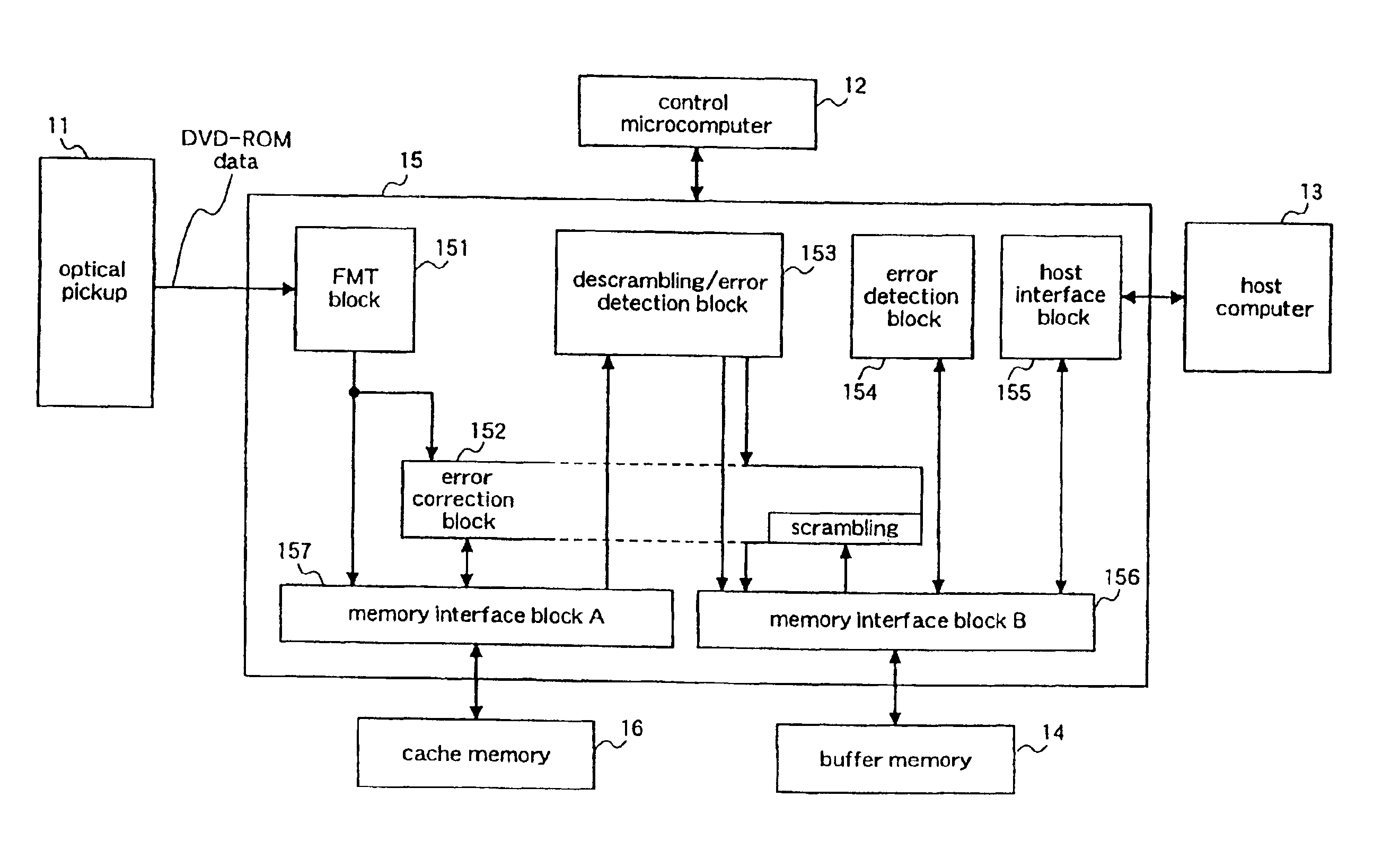
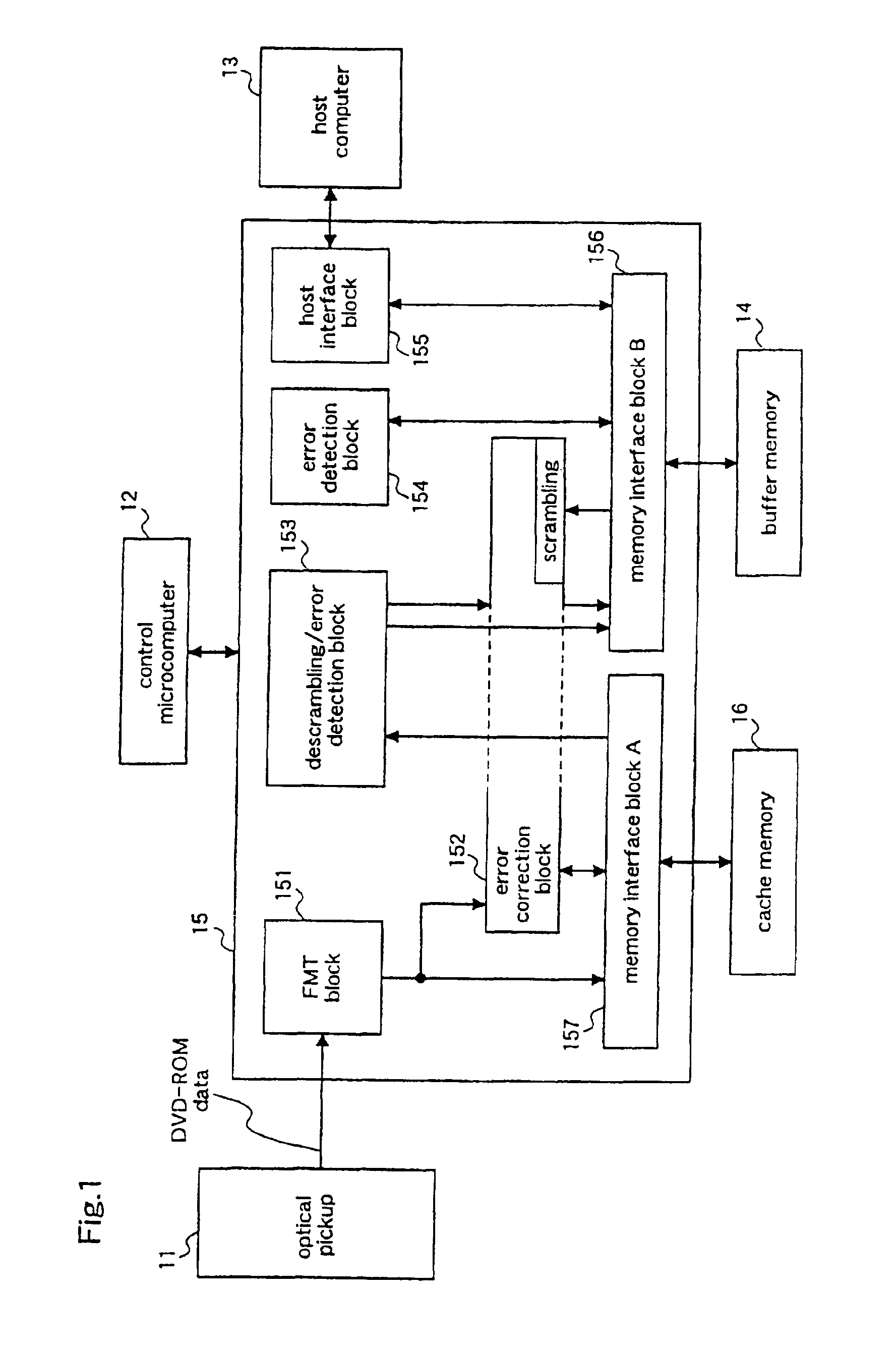
[0034]FIG. 1 is a block diagram illustrating the structure of a DVD-ROM signal processor according to a first embodiment of the present invention.

[0035]In FIG. 1, a DVD-ROM signal processor 15 receives DVD-ROM digital signal data (hereinafter referred to as “data”) which is read by an optical pickup 11, and outputs the data after error correction to a host computer 13. The DVD-ROM signal processor 15 is controlled by a control microprocessor (controller) 12, and the DVD-ROM signal processor 15 is connected to a cache memory 16 for storing the data and to a buffer memory 14 for storing the data stored in the cache memory 16.

[0036]To be specific, the DVD-ROM signal processor 15 is provided with an FMT block 151 for capturing the DVD-ROM data outputted from the optical pickup 1; an error correction block 152 for correcting errors in the data stored in the cache memory 16 and the buffer memory 14; a descrambling / error detection block 153 for descrambling the scrambled data, and detectin...

embodiment 2

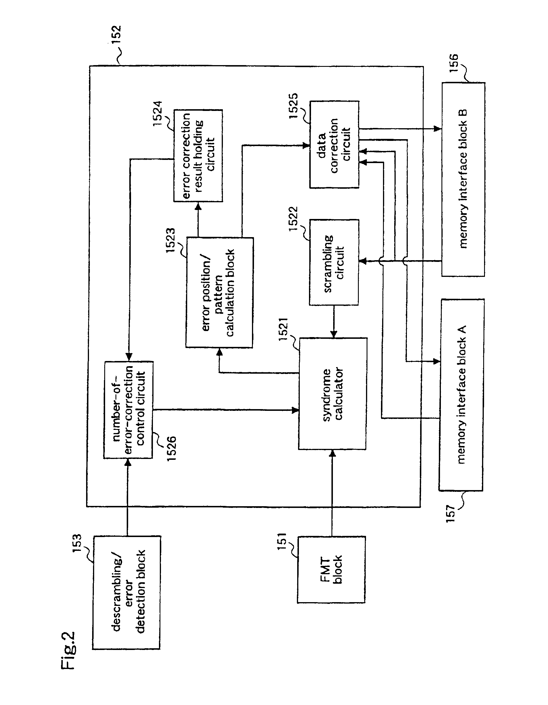
[0045]FIG. 2 is a block diagram illustrating the internal structure of an error correction block according to a second embodiment of the present invention.

[0046]With reference to FIG. 2, an error correction block 152 is provided with. a syndrome calculator 1521 for performing syndrome calculation; a scrambling circuit 1522 for scrambling descrambled data; an error position / pattern calculation block 1523 for calculating an error position in data and an error pattern on the basis of the result from the syndrome calculator 1521, and detecting data having uncorrectable errors (hereinafter referred to as “error uncorrectable data”); an error correction result holding circuit 1524 for holding information as to whether there is error uncorrectable data or not, which is detected in the error position / pattern calculation block 1523; data correction circuit 1525 for correcting errors in the data according to the error position and the error pattern calculated from the syndrome by the error po...

embodiment 3

[0056]FIG. 3 is a block diagram illustrating the internal structure of a descrambling / error detection block according to a third embodiment of the present invention.

[0057]In FIG. 3, a descrambling / error detection block 153 is provided with a descrambling circuit 1531 for descrambling scrambled data; an error detection circuit 1532 for detecting errors in the descrambled data; and an error detection result holding circuit 1533 for holding the result of error detection (presence or absence of error) by the error detection circuit 1532.

[0058]The operation of the descrambling / error detection block so constructed will be described with reference to FIG. 3.

[0059]Initially, the data which has been subjected to error correction in the error correction block 152 is inputted to the descrambling circuit 1531 from the cache memory 16 through the memory interface block A 157, and the data is descrambled according to a predetermined method. The descrambled data is transmitted to the error detecti...


PUM


Abstract

A signal processor performs error correction on data which has been subjected to predetermined signal processing, for each predetermined block unit, by an error correction block, in parallel with an operation of sequentially storing the data in a cache memory. Then, error detection is performed on the data for each predetermined block unit by a descrambling / error detection block, and the data is stored in a buffer memory. Based on the results of the error detection and the error correction, when there exists some error in the data, the data with the error, which is stored in the buffer memory, is read out to be subjected to error correction again. When there is no error, the data corresponding to one block and stored in the buffer memory is transmitted to a host computer without performing error correction again.

Description

TECHNICAL FIELD[0001]The present invention relates to a signal processor for detecting and correcting errors in data read from a recording medium.BACKGROUND ART[0002]In recent years, high quality and high speed are demanded of a DVD-ROM, which has become widespread as a digital memory, to increase the reliability of data read from a DVD disk. With the demand, a signal processor for correcting errors in the disk is required to have rapid processing means, and it is aimed at realization of high-speed data processing.[0003]A conventional CD-ROM signal processor performs error correction by a predetermined number of times. Further, the CD-ROM signal processor writes inputted data in a buffer memory and, simultaneously, detects errors in the data by using CRC (Cyclic Redundancy Check). Based on the result of CRC, when the data is decided as “error-free data”, the signal processor reduces the predetermined number of error corrections.[0004]In the case of DVD-ROM data, however, since input...

Claims


Application Information

Patent Timeline
IPC IPC(8): G11B20/18H03M13/00H03M13/15H03M13/29H03M13/27
CPCG11B20/1833G11B20/1866H03M13/6566H03M13/2924H03M13/2927H03M13/1515G11B20/18
Inventor AOKI, TORU
Owner PANASONIC CORP
Learn More