
Inductively coupled stress/strain sensor

a stress/strain sensor and inductive coupling technology, applied in the direction of mechanical measuring arrangement, instruments, using mechanical means, etc., can solve the problems of tragic consequences, unforeseen alteration of the factor of safety, and incorrect computation models of stress and strain

Inactive Publication Date: 2005-07-05
SENSORTEX
View PDF13 Cites 60 Cited by
  • Summary
  • Abstract
  • Description
  • Claims
  • Application Information

AI Technical Summary

Benefits of technology

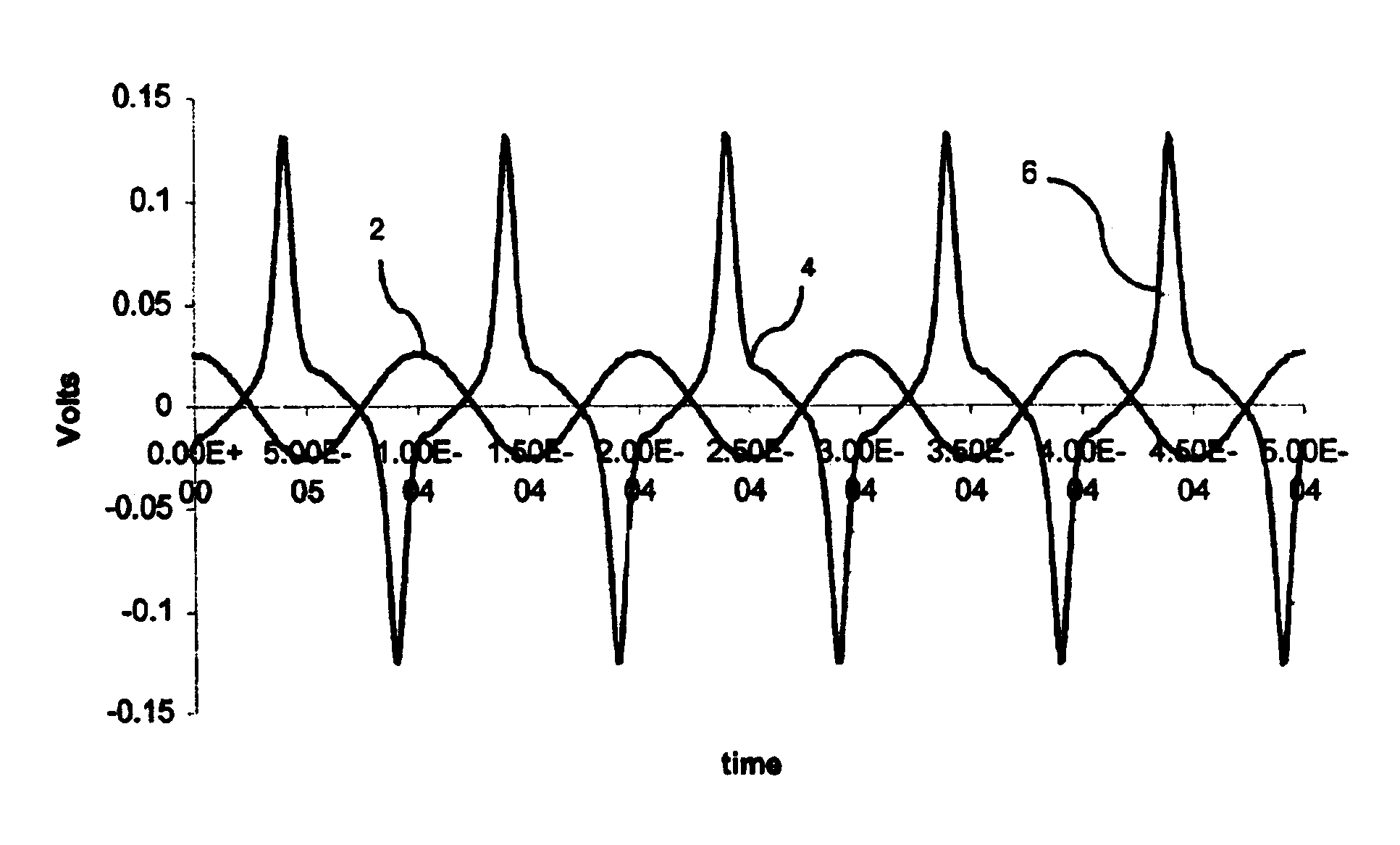
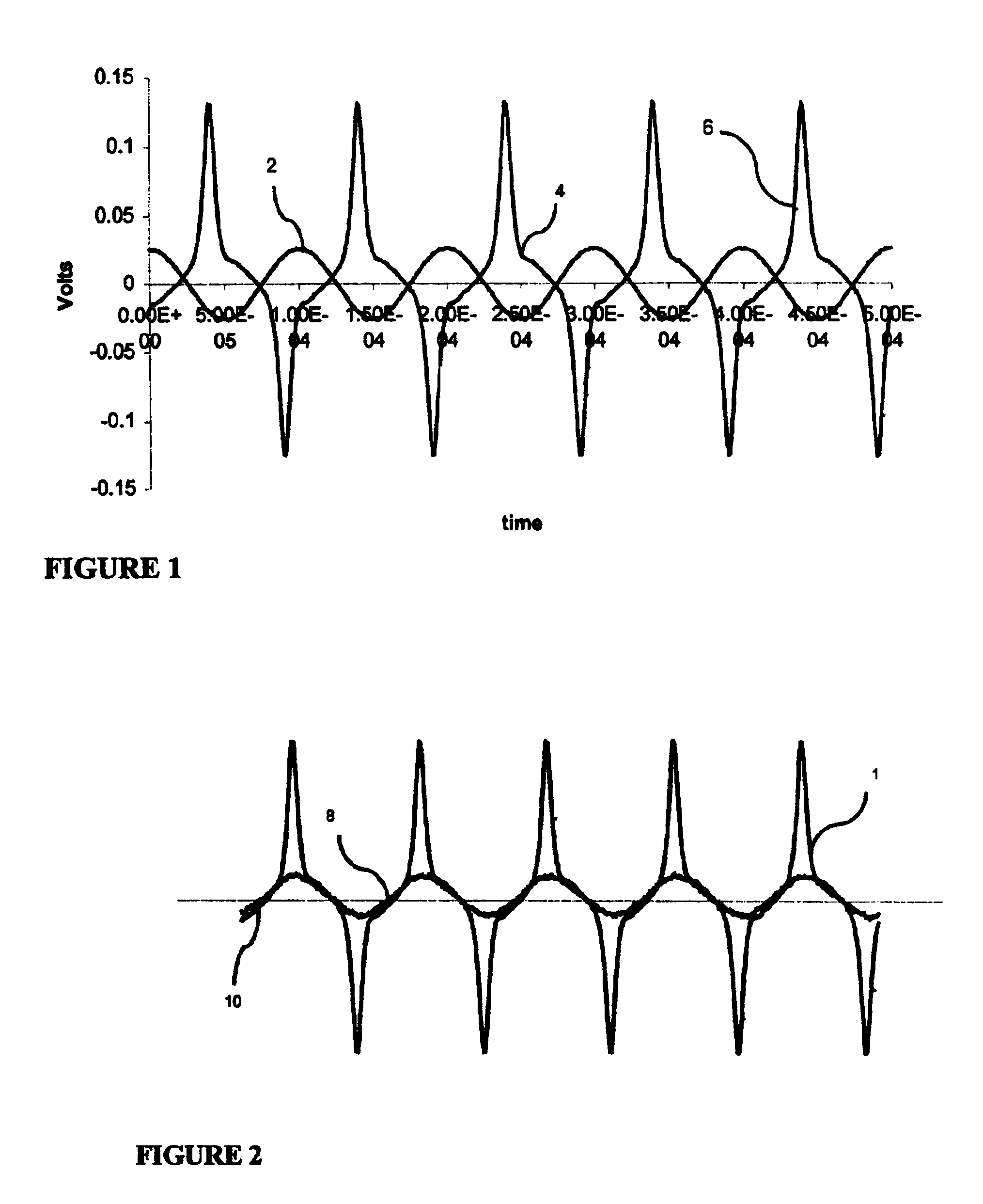
[0017]It is another objective, aspect and advantage of the present invention to provide and teach a method wherein the first current further comprises an AC current having a first frequency.
[0018]It is another objective of the present invention to provide a method wherein the second current further comprises a second frequency component which is a harmonic of the first frequency.
[0019]It is another objective of the present invention to provide a method wherein the strain sensor has an inductance which changes with strain.
[0020]It is another objective and embodiment of the present invention to provide a method wherein the strain sensor changes its voltage-current relationship with strain.
[0021]It is another objective of the present invention to provide a method wherein the strain sensor comprises a wire coated with a magnetostrictive film, the wire having two ends.
[0022]It is another objective and embodiment of the present invention to provide a method wherein the strain sensor further comprises at least one induction loop operatively connected to each end of the wire.

Problems solved by technology

Despite the existence of well known theories for calculation of stress or strain, measurement remains vital because even in recent decades, computational models of stress and strain have been shown to be incorrect by strain and stress factors which may even exceed the ultimate / design load (working load times the factor of safety) originally provided.
In addition, even when such models are correct, decisions made at the time of manufacture or construction may alter the factor of safety in unforseen ways, occasionally with tragic consequences.
Finally, during the life cycle of such bodies, fatigue and other alterations in the structure's composition, the history of use of the body or other changes may change the stress or strain of the body.
Traditional sensors are simply devices (such as wires) firmly attached to the body to be measured, so that elongation of the body results in elongation of the sensor.
However such sensors typically require an electronic connection to the measuring apparatus being used to record the measured strain / stress.
For example, measuring torque on a rotating shaft is a complex problem: the rotation of the shaft may make a physical contact impossible; other considerations such as space may make telemetry impossible.
However, it does not teach remote magnetic induction of a self-current in the sensor, nor remote sensing of the magnetic field internally generated by the sensor's self-current.
. . ” Thus switches may not serve as useful prior art to sensors and in addition, various structural features of these two references result.
In addition, the current applied is minuscule, and the wire used is copper-beryllium, having a resistance too high to allow useful spike measurement.
However, the '439 patent does not disclose that a harmonic frequency of the basic resonance frequency may be sensed, nor does the '439 patent teach or suggest the use of a simplified sensor having a non-linear current-voltage relationship.
This assemblage is obviously not always practical, given considerations such as space, and the presence of the rotor / stator / slip ring / leaf contact combination may substantially alter the rotation of the body being measured.
This is a fixed installation, once again requiring a large space, and severely impacting the geometry of the body being measured.
In many applications, contact between the sensing system and the body monitored is undesirable or impossible.
In other applications such as bridges, long term health monitoring is needed, yet wear and damage on sensors may mount quickly if the sensor is properly placed to monitor structural elements in high traffic zones or high weather impact zones.
In addition, known non-contact stress measurement systems suffer from a variety of weaknesses including weak signal strength, difficulty of sorting out the signal from noise, power requirements, and so on.

Method used


Image

  • Inductively coupled stress/strain sensor
  • Inductively coupled stress/strain sensor
  • Inductively coupled stress/strain sensor

Examples


example ii

[0070]FIG. 7 is a circuit diagram of a third embodiment of the invention showing the circuitry used to drive and monitor the sensor. Oscillator 34 generates a 10 kHz base excitation signal. Op amp 36 boosts the power of the 10 KHz excitation signal sent to remote excitation coil 38. Excitation coil 38 is an 80 turn coil in operative proximity to the sensor (not depicted). Sensing coil 40, which is in operative proximity to the sensor (not depicted) receives therefrom the non-linear signal and is a 10 turn coil connected to a demodulator system. The number of turns in each coil is neither fixed to the values above nor optimized; other values are possible.

[0071]While the excitation current in Example II is of 10 kHz frequency, the invention is not so limited, and frequencies from 0 to 1 MHz may be used, preferably in the range from 500 Hz to 250 kHz, more preferably in the range from 1 to 100 kHz, most preferably approximately 10 kHz.

[0072]The demodulator system comprises PLL 42 (a ph...


PUM


Abstract

An improved method of sensing strain allows measurements of stress, torque, vibration and other loads imposed on a body without physical contact between the body / sensor and the monitoring equipment. An induction loop is at least partially comprised of a magnetostrictive material with a non-linear current-voltage relationship. An excitation device such as a coil is used to induce an AC response in the sensor. The non-linear response to the induced current is received by a sensing device such as a sensing coil, and the output thereof is filtered. The excitation device and sensing device are located in operative proximity to the sensor, but need not be in contact therewith, allowing easy measurement in small spaces, under harsh conditions, or of moving bodies such as drive shafts. The non-linear response of the sensor induces easily detectable harmonics of the base frequency of excitation. These harmonics may advantageously be measured as well.

Description

FIELD OF THE INVENTION[0001]This invention relates generally to stress / strain and torque measurement and more specifically to measurement of stress / strain without physical contact, using a stress / strain / torque sensitive sensor having a non-linear voltage-current relationship.BACKGROUND OF THE INVENTION[0002]Measurement of stress and strain in various types of bodies is a critical task in numerous fields of engineering. Mechanical, civil, and aeronautical engineers, designers working in many areas and those in charge of monitoring long term status of structures and devices all require the ability to check theoretical calculations of stress or strain against actual measurement of these factors. Machinery, vehicles, buildings, structures, precision equipment, even certain geological structures are all examples of the types of bodies on which stress / strain measuring is used. Despite the existence of well known theories for calculation of stress or strain, measurement remains vital becau...

Claims


Application Information

Patent Timeline
IPC IPC(8): G01L5/22G01L3/10G01L1/12
CPCG01L3/102G01L1/127G01L1/125G01L3/105
Inventor OH, SUNG J.BITER, WILLIAM J.HESS, STEPHEN M
Owner SENSORTEX
Learn More