Ion enrichment aperture arrays

a technology of aperture arrays and apertures, applied in electron/ion optical arrangements, particle separator tube details, separation processes, etc., can solve the problems of low electrostatic field penetration into the lower pressure region relative to larger apertures with higher conductance, more sensitive response of ion analyzers or higher currents

Inactive Publication Date: 2005-07-05
CHEM SPACE ASSOIATES
View PDF3 Cites 76 Cited by
  • Summary
  • Abstract
  • Description
  • Claims
  • Application Information

AI Technical Summary

Problems solved by technology

Conversely, this device has higher transmission of ions for a given total gas load on the lower pressure region resulting in more sensitive response for ion analyzers or higher currents for current deposition processes.
Utilizing small apertures in the arrays results in very low electrostatic field penetration into the lower pressure region relative to larger apertures with higher conductance.

Method used


Image

  • Ion enrichment aperture arrays
  • Ion enrichment aperture arrays
  • Ion enrichment aperture arrays

Examples


Embodiment Construction

—FIGS. 1 AND 2—PREFERRED EMBODIMENT

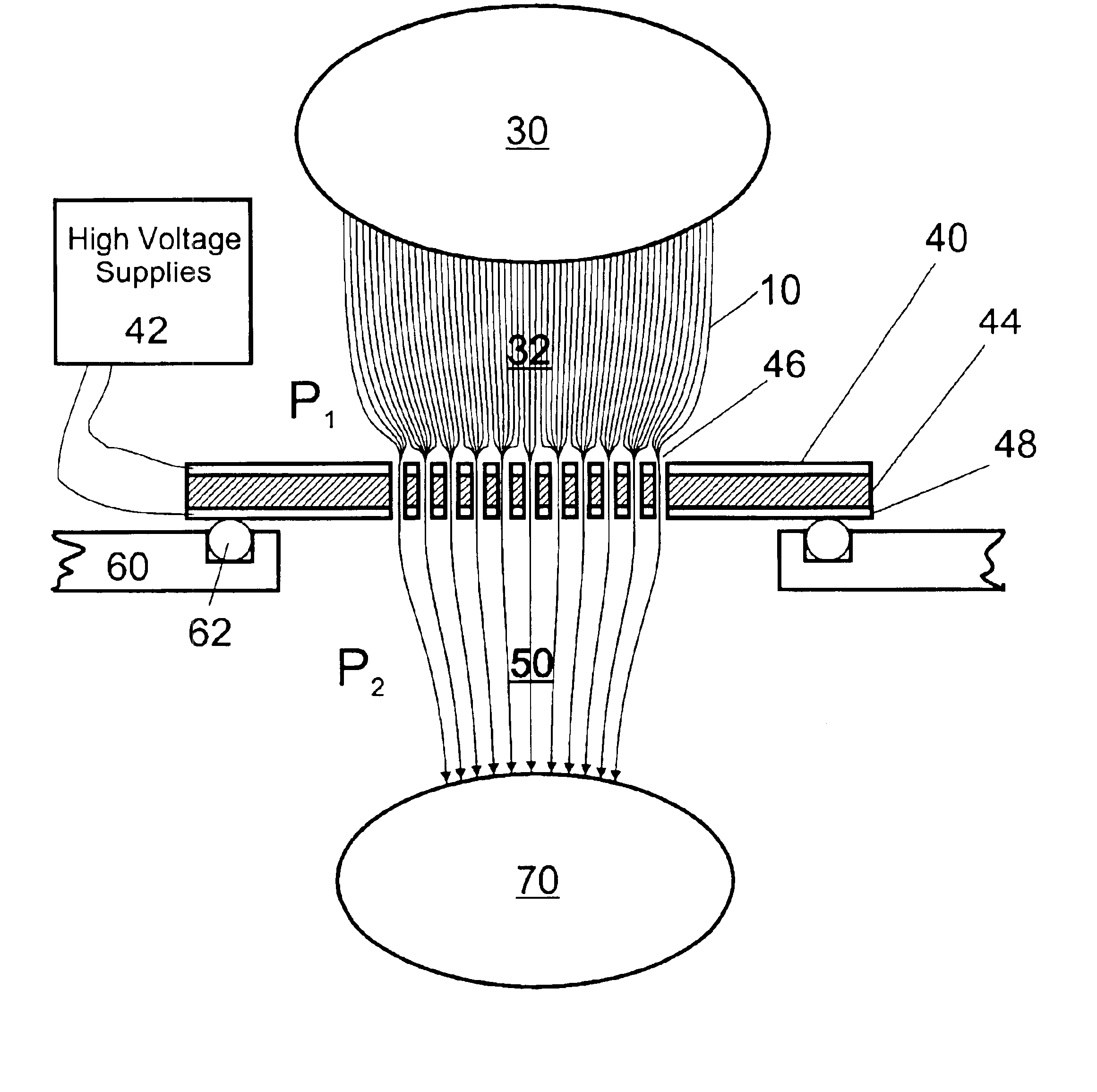
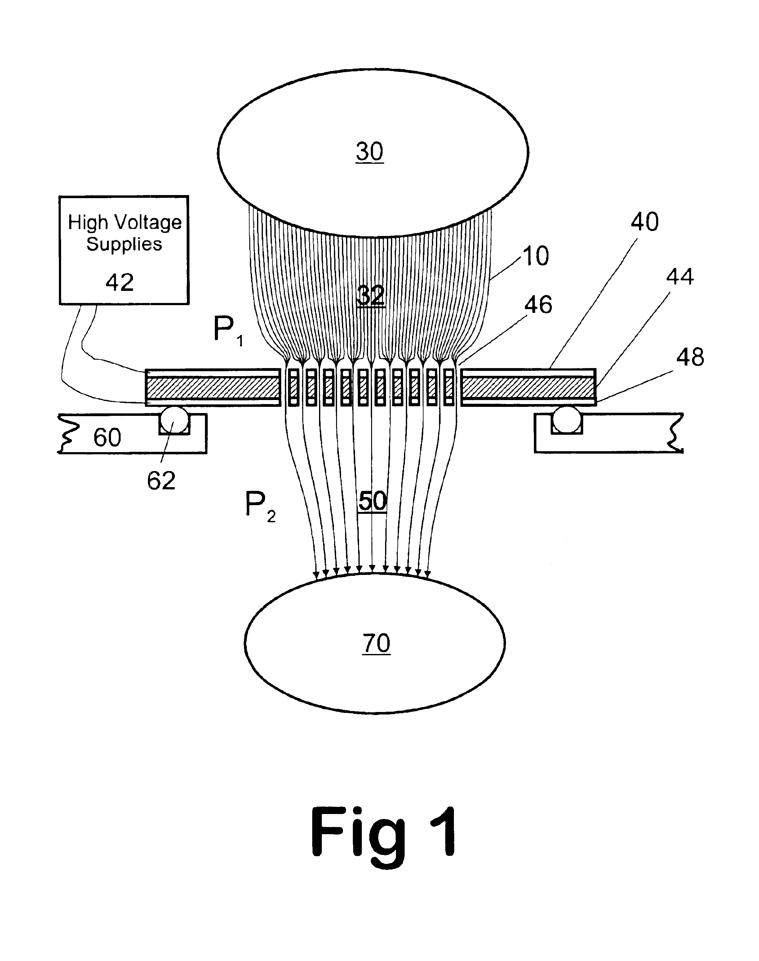
[0066]A preferred embodiment of the ion selective multi-aperture laminate of the present invention is illustrated in FIGS. 1 and 2. The multi-aperture laminate has a thin first insulated laminate 44 of uniform cross section consisting of an insulating material. A layer of metal 40 and 48 is laminated on both sides of the laminate 44. In the preferred embodiment, 44 is an insulating material, such as glass or ceramic. However, it can consist of any other material that can isolate electrically the two metal laminates 40 and 48 from each other, such as nylon, polyimide, Teflon, poly ether ether ketone (PEEK), etc.

[0067]The multi-aperture lens is populated with many holes or apertures 46 that traverse the lens leading from higher pressure ion collection region 32 to lower pressure region 50. The inlets of the apertures 46 are downstream of the ion source region 30 and ion collection region 32. The inlets accept ions from the region 32. The ions are tra...


PUM


Abstract

Improvements have been made for collecting, focusing, and directing of ions and / or charged particles generated at atmospheric or near atmospheric pressure sources, such as but not limited to, electrospray; atmospheric pressure discharge ionization, chemical ionization, photoionization, and matrix assisted laser desorption ionization; and inductively coupled plasma ionization. A multiple-aperture laminated structure is place at the interface of two pressure regions. Electric fields geometries and strengths across the laminated structure and diameters of the apertures; all of which act to optimize the transfer of the ions from the higher pressure region into the lower pressure region while reducing the gas-load on the lower pressure region. Embodiments of this invention are methods and devices for improving sensitivity of mass spectrometry when coupled to atmospheric, near atmospheric, or higher pressure ionization sources by reducing the gas-load on the vacuum system.

Description

CROSS-REFERENCE TO RELATED APPLICATIONS[0001]This application is entitled to the benefit of Provisional Patent Application Ser. No. 60 / 476,582, filed Jun. 7, 2003. This application is related to Provisional Patent Application Ser. No. 60 / 210,677, filed Jun. 9, 2000, and patent application Ser. No. 09 / 877,167, filed Jun. 8, 2001, now U.S. Pat. No. 6,744,041, issued Jun. 1, 2004; Provisional Patent Application Ser. No. 60 / 293,648, filed May 26, 2001, now patent application Ser. No. 10 / 155,151, filed May 25, 2002; Provisional Patent Application Ser. No. 60 / 384,869, filed Jun. 1, 2002, now patent application Ser. No. 10 / 499,147, filed May 31, 2003; Provisional Patent Application Ser. No. 60 / 410,653, filed Sep. 13, 2002, now patent application Ser. No. 10 / 661,842, filed Sep. 12, 2003; Provisional Patent Application Ser. No. 60 / 419,699, filed Oct. 18, 2002, now patent application Ser. No. 10 / 688,021, filed Oct. 17, 2003; and Provisional Patent Application Ser. No. 60 / 476,576, filed Jun. 7...

Claims


Application Information

Patent Timeline
Patent Type & Authority Patents(United States)
IPC IPC(8): B01D59/44B01D59/00H01J49/02H01J49/00H01J49/06B01DH01J49/10
CPCH01J49/067H01J49/0404
Inventor SHEEHAN, EDWARD W.WILLOUGHBY, ROSS C.
Owner CHEM SPACE ASSOIATES
Why Eureka
Try Eureka