
Method for detecting extended range motion and counting moving objects using an acoustics microphone array

a technology of acoustic microphone array and acoustic microphone, which is applied in the direction of direction finders, instruments, systems with undesired wave elimination, etc., can solve the problems of confusion, complex data association logic is required to sort, and noisy, and achieves high-quality vehicle counting, reducing (and often canceling) the effects of interfering signals

Inactive Publication Date: 2005-07-05
UNITED STATES OF AMERICA THE AS REPRESENTED BY THE SEC OF THE ARMY
View PDF1 Cites 106 Cited by
  • Summary
  • Abstract
  • Description
  • Claims
  • Application Information

AI Technical Summary

Benefits of technology

[0016]The present method represents a new approach to the problem of counting targets using one or more acoustic arrays and can effectively count targets without human intervention. The present method allows the addition of an “acoustic trip line counter” around a surveillance area as a “building block” for each acoustic node placed in the area. The user implements the present method by selecting a look direction across which the “motion detection” and resulting counting may occur. Two or more acoustic arrays that look down the same avenue can extend the range of the “acoustic trip line” to cover large battlefield frontage. Measurements are partitioned into sets of observations and are confirmed so that background noise and other false detections are rejected while estimates for the number of targets can be computed. While the present invention is discussed in terms of vehicles in a battlefield situation, the present invention can be applied to moving objects in any scenario.
[0017]In many projected remote sensor deployment concepts, there exists a need to form a perimeter around the sensor surveillance area. Implementation of the present method allows the formation of an effective surveillance perimeter using multiple acoustic sensor nodes. The information from the present method is useful as a powerful stand-alone technique to count targets in specific surveillance zones. The present method may also be added to existing system level tracking solutions implemented for the purpose of better defining the location of multiple vehicles in confusing multiple vehicle scenarios.
[0019]The present method introduces a way of alleviating uncertainties regarding the number of vehicles being tracked at closest point of approach based solely on individual sensor information. The performance of the present method is ensured using signal processing techniques that provide the capability of both detecting the presence of every vehicle that approaches an acoustic array and obtaining a highly accurate vehicle count.
[0020]In dense target environments, the detected acoustic signals are contaminated by the engine noise from other vehicles that are often louder than the target of interest. The problem of separating signals from individual targets in multiple target scenarios requires a robust adaptive approach to suppress interference from other vehicles closely spaced to the target of interest. The present method solves this issue through an acoustic “trip line” algorithm that addresses problems with the array's limited resolution due to its finite aperture. The method also introduces noise suppression that excludes undesired signals and overcomes the inability to account for source motion.
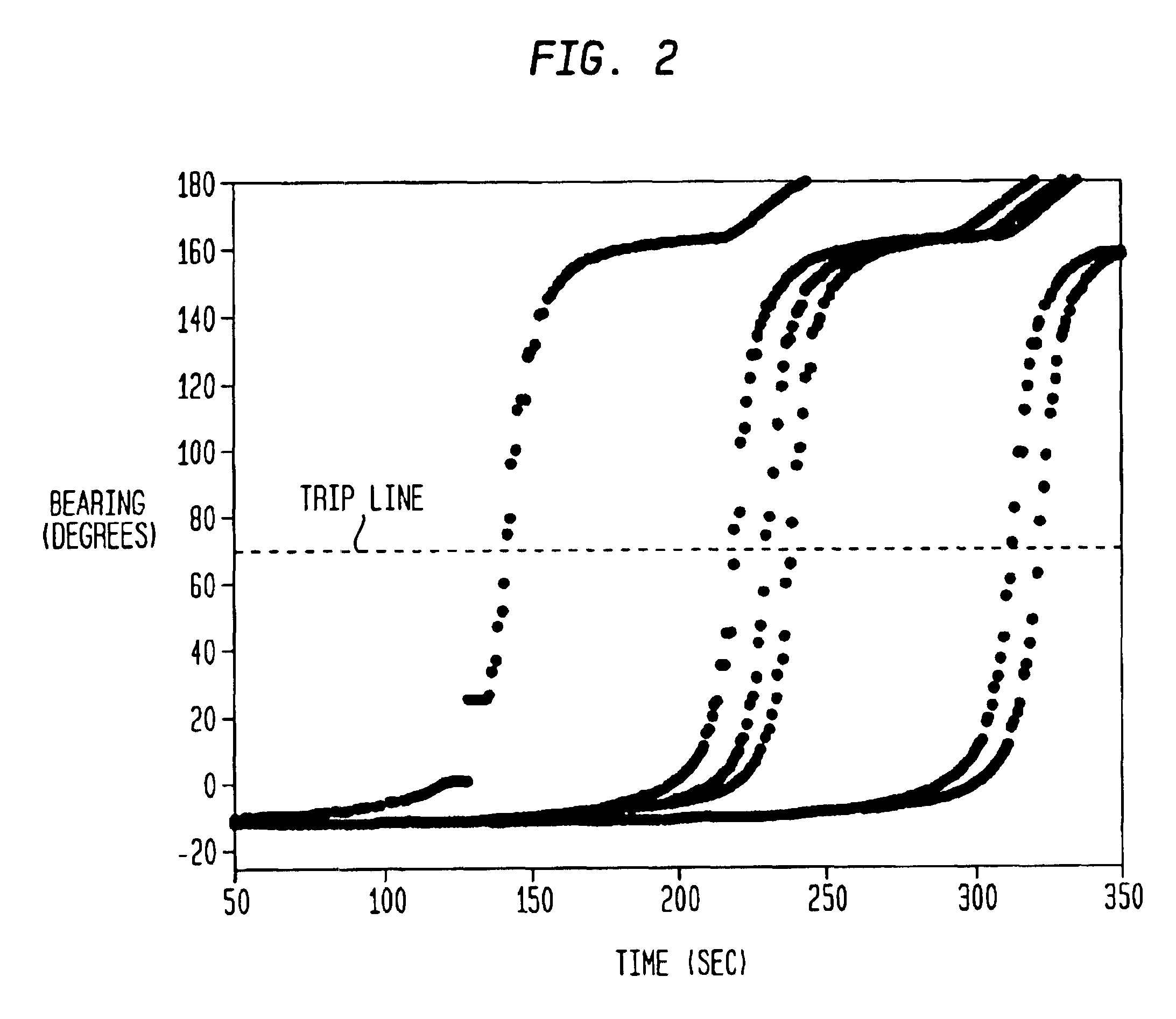
[0021]An implementation of the “trip line” approach of the present method utilizes both conventional and adaptive beamforming algorithms that form a refined spatial filter to capture the harmonic content (key features) of individual targets that pass through a fixed line in bearing. The power from narrowband signal components in both the conventionally and adaptively formed beams is monitored so that a target crossing a line of bearing through one of the designated beams triggers the event of a target count. Conventional beamforming is used to “coarsely” filter and estimate the direction of arrival of narrowband acoustic sources impinging on the circular array of microphones. The “fixed” beam pointing and highly selective spatial filtering is achieved using a minimum variance distortionless response (MVDR) beamforming algorithm in which the spatial filtering function is frequently updated in response to changes in the local environment. This adaptive weight computation ensures a beamformer response that approaches the theoretically optimum solution by reducing (and often canceling) the effects of interfering signals. Significant performance advantages are gained using the adaptive beamforming algorithm. The adaptive strategy also accounts for movements in source direction by frequently updating the spatial characteristics of the array to obtain an optimal signal to noise gain in the direction of the target.

Problems solved by technology

However, complex data association logic is required to sort out sensor measurements into general categories such as targets of interest, sources that are not of interest and false detections that cannot be correlated over time.
Target tracking in noisy, cluttered environments is treated as a problem in associating detected target observations with target tracks.
One of the most challenging areas of the multi-sensor performance problem is the beam-pointing control of an acoustic array in dense multiple target environments, where closely spaced targets, highly maneuvering targets, and targets in the presence of multi-path should be resolved.
Consequently, if more than N−1 targets enter the surveillance area, confusion potentially exists and the ability to individually track each vehicle cannot be maintained.
In practice, a basic problem of accountability occurs when a count for the number of targets that pass by the vicinity of the acoustic array is desired.
Often, the tracks are not maintained continuously and without high fidelity (depending on range from the array and spacing of targets).
Consequently, it is difficult to know which tracks should be “counted”.
If more than one acoustic array is required to cover a greater area, accountability of target count becomes very difficult.
Deciding if the target is the same target being viewed from multiple remote locations is inherently difficult, often creating “ghost” targets, which are targets that don't exist.
In scenarios where targets are closely spaced or moving abreast relative to a sensor node, the sensors do not “hear” the same target over portions of the track through the sensor field, therefore, tracking and target counting accountability is very difficult.
The need for such a system has heretofore remained unsatisfied.

Method used


Image

  • Method for detecting extended range motion and counting moving objects using an acoustics microphone array
  • Method for detecting extended range motion and counting moving objects using an acoustics microphone array
  • Method for detecting extended range motion and counting moving objects using an acoustics microphone array

Examples


Embodiment Construction

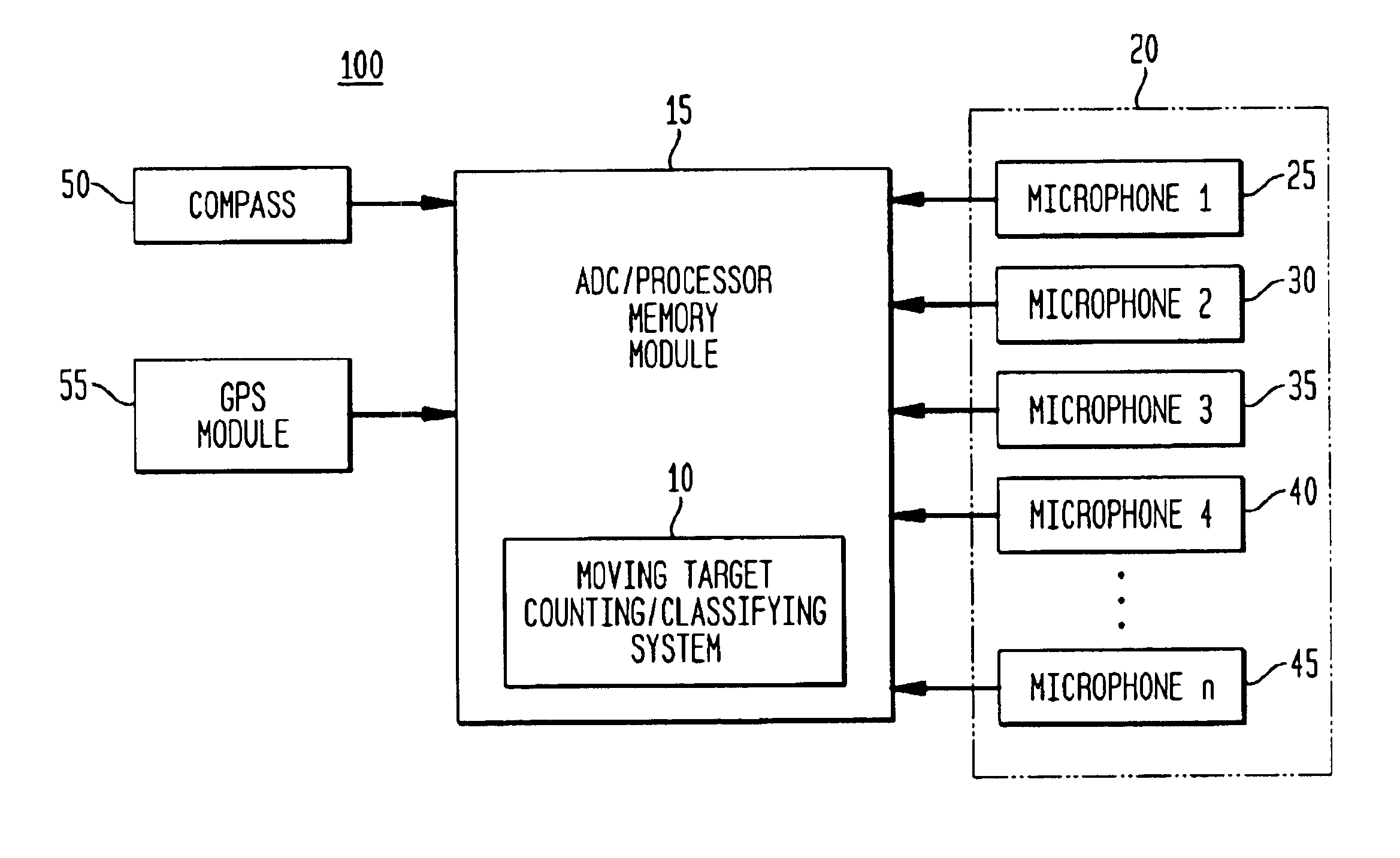
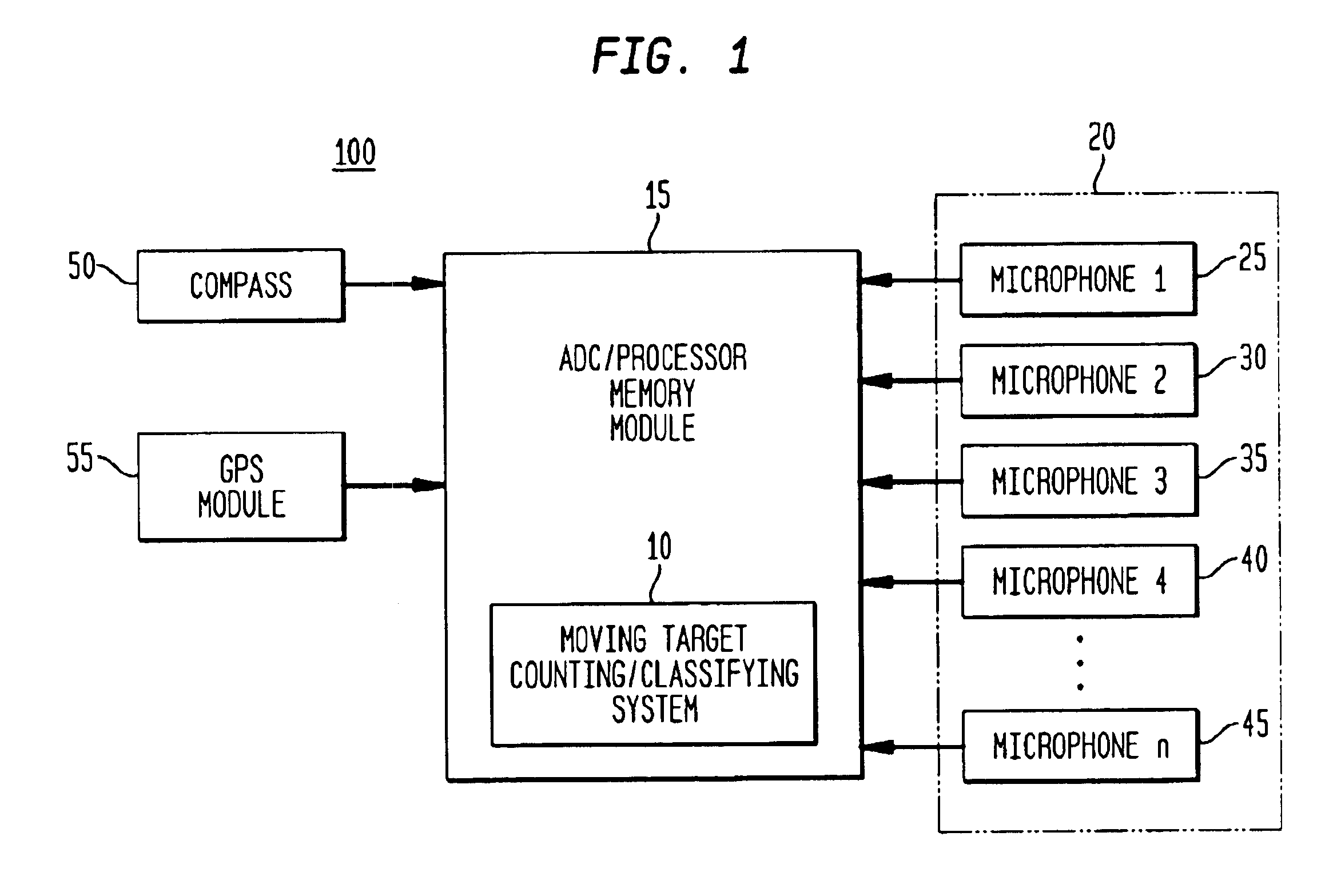
[0029]FIG. 1 illustrates an exemplary high-level architecture of an acoustic sensor system comprising a moving target counting system 10 that utilizes an algorithm for detecting extended range motion and counting moving objects using an acoustics microphone array. System 10 includes a software programming code or computer program product that is typically embedded within, or installed on an Analog to Digital Converter (ADC) / Processor memory module 15. The microphone array 20 comprises a set of microphones such as microphone 1—(#25), microphone 2—(#30), microphone 3—(# 35), microphone 4—(#40), up to and including microphone n—(# 45). The microphone array 20 provides acoustic information to system 10 for detecting, tracking, counting and classifying targets. The compass 50 and GPS module 55 also provide information to the system 10 for location and steering purposes.

[0030]An acoustic sensor system can be used to perform direction finding using a fixed array strategy to optimize the fi...


PUM


Abstract

An acoustic array platform comprising multiple spaced microphones and associated processing electronics / algorithms projects distinct beams in a chosen look direction across which moving objects such as vehicles pass. These moving objects are accurately detected, classified and counted at extended ranges. The acoustic microphone array employs optimized beamforming to create specially focused listening directions that function as a “motion detector” and “trip line counter”. Algorithms detect and confirm the appropriate presence of objects moving through the beams and perform other algorithmic tests to verify that the object is a valid object to be counted. The proposed approach is realized with modest sized acoustic arrays and a reasonable number of microphones by employing an adaptive beamforming algorithm that achieves enhanced directivity in a principal look direction and which significantly reduces the effects of interferers outside the precise steering direction of the “trip line”.

Description

CROSS REFERENCE TO RELATED APPLICATIONS[0001]This application claims benefit under 35 USC 119(e) of provisional application 60 / 319,652 filed Oct. 29, 2002 and of provisional application 60 / 320,214 filed May 23, 2003, the entire file wrapper contents of which provisional applications are herein incorporated by reference as though fully set forth at length.FEDERAL RESEARCH STATEMENT[0002]The invention described herein may be made, used, or licensed by or for the for U.S. Government for U.S. Government purposes.BACKGROUND OF INVENTION[0003]1. Field of the Invention[0004]This invention generally relates to detection of moving targets, and more specifically to detection of moving targets using one or more acoustic arrays. More particularly, this invention pertains to a system that uses conventional and / or adaptive beamforming to locate and count multiple targets in dynamic, noisy, and highly mobile environments.[0005]2. Background of the Invention[0006]Acoustic over watch sensor systems ...

Claims


Application Information

Patent Timeline
IPC IPC(8): G01S3/80G01S3/00G01S3/86G01S11/14
CPCG01S3/8006G01S11/14G01S3/86
Inventor HEBERLEY, JEFFREY R.HOHIL, MYRON M.CHANG, JAY W.ROTOLO, ANTHONY G.
Owner UNITED STATES OF AMERICA THE AS REPRESENTED BY THE SEC OF THE ARMY
Learn More