Light source device and projection type display unit to which the device is applied

Active Publication Date: 2005-07-12
RAKUTEN GRP INC
View PDF8 Cites 42 Cited by
  • Summary
  • Abstract
  • Description
  • Claims
  • Application Information

AI Technical Summary

Benefits of technology

[0031]According to the embodiment, for the light guide, the parallel inner wall surfaces facing each other are formed following the portion obtained by narrowing down a part of the inner wall surface in order to emit the light (or each color light) converged by the condensing lens while repeatedly reflecting the light by the mirror surface. Therefore, the light source image having the nonuniform distribution by the light (or the respective color lights)

Problems solved by technology

That is, for a first problem, the lens arrays 204R, 204G, 204B for R, G, B are required for the LED arrays 203R, 203G, 203B for the RGB colors, the dichroic prism 201 which is very expensive needs to be used, and it is difficult to reduc

Method used


Image

  • Light source device and projection type display unit to which the device is applied
  • Light source device and projection type display unit to which the device is applied
  • Light source device and projection type display unit to which the device is applied

Examples


embodiment 1

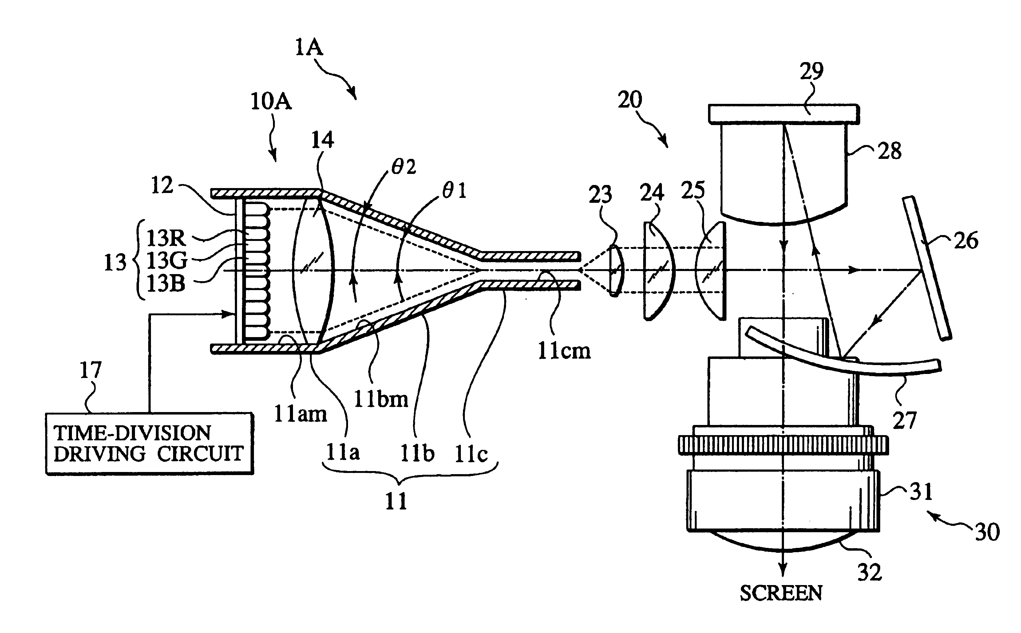
[0057]As shown in FIGS. 3 and 4, a projection type display unit 1A of Embodiment 1 according to the present invention schematically comprises: a light source device 10A in which a light emitted from a semiconductor light emitting device array 13 attached onto a rectangular substrate 12 in a light guide 11 is converged by a convex lens 14 functioning as a condensing lens and emitted; an image display part optical system 20 which irradiates an image display device (hereinafter referred to as DMD) 29 with the light emitted from the light source device 10A; and a projection part optical system 30 which projects an image light displayed on the DMD 29.

[0058]That is, in the light source device 10A of Embodiment 1 according to the present invention, a large quadratic prism portion 11a largely opened in a large quadrangular shape is formed on a light incidence port side of the light guide 11, a quadrangular pyramid portion 11b whose inner wall surface is narrowed down toward a light emission...

embodiment 2

[0080]In this case, even in the light source device 10B of Embodiment 2, for the red (R) light, green (G) light, and blue (B) light emitted from the red LED 13R, green LED 13G, blue LED 13B constituting the LED array 13, the beam area is reduced in accordance with a condensing angle θ1′ of the Fresnel lens 15 every time-divisional driving. However, in this case, when an inclination angle θ2′ of the quadrangular pyramid portion 11b of the light guide 11 is set to be substantially equal to the condensing angle θ1′ of the Fresnel lens 15, the each color light from the LED array 13 can be converged with good efficiency.

[0081]Accordingly, the projection type display unit 1B to which the light source device 10B is applied can also be miniaturized. Needless to say, the light source device 10B and the projection type display unit 1B to which the light source device 10B is applied can obtain an effect similar to that of Embodiment 1.

[0082]FIG. 10 is a constitution diagram showing the light s...

embodiment 3

[0084]That is, as shown in FIG. 10, the projection type display unit 1C of Embodiment 3 substantially comprises the light source device 10C, image display part optical system 20, and projection part optical system 30, and only the light source device 10C is different from Embodiments 1 and 2.

[0085]In the light source device 10C, as shown in FIGS. 10 to 12, the LED array 13 is attached to the rectangular substrate 12 in the large quadratic prism portion 11a on the light incidence port side of the light guide 11 in the same manner as in Embodiments 1, 2. The present embodiment is different from Embodiments 1, 2 in that a toroidal lens 16 is attached as the condensing lens for condensing each color light emitted from the LED array 13. Therefore, the LED array 13 and toroidal lens 16 are arranged in that order toward the light emission port side on the light incidence port side inside the light guide 11.

[0086]The toroidal lens 16 is a biaxial lens including a donut-shaped lens surface. ...


PUM


Abstract

A light emitted from a semiconductor light emitting device array having a plurality of semiconductor light emitting devices arranged two-dimensionally on a substrate is converged by a condensing lens. In a light guide, a mirror surface is formed from a light incidence port to a light emission port along an inner wall surface. The semiconductor light emitting device array and the condensing lens are arranged in that order toward the light emission port inside the light incidence port of the light guide. A part of the inner wall surface of the light guide is narrowed down substantially along a condensing angle of the condensing lens. The light guide includes parallel inner wall surfaces facing each other, following a portion obtained by narrowing down a part of the inner wall surface, in order to emit the light (each color light) converged by the condensing lens while repeatedly reflecting the light on the mirror surface.

Description

BACKGROUND OF THE INVENTION[0001]1. Field of the Invention[0002]The present invention relates to a light source device capable of securing uniformity of in-plane luminance of light emitted from a semiconductor light emitting device array, and a projection type display unit to which the light source device is applied.[0003]2. Description of the Related Art[0004]In recent years, there has been well used a projection type display unit for displaying, in a large screen, a high-precision color image represented by high vision broadcasting standards, ultra extended graphics array (UXGA) standards of computer graphics or the like.[0005]The projection type display unit includes a unit to which a transmission type or reflection type space optical modulation device (e.g., a liquid crystal panel) is applied as an image display device for displaying a color image, a unit to which a digital micromirror device (DMD) is applied, and the like. Furthermore, there are a single plate system in which t...

Claims


Application Information

Patent Timeline
IPC IPC(8): G03B21/20G02B6/00H01L33/56H01L33/58H01L33/60
CPCG03B21/2013G03B21/2066G03B21/2033Y10S385/901
Inventor OMODA, MANABUMIYAMOTO, RITSU
Owner RAKUTEN GRP INC
Why Eureka
Try Eureka