Modular barrier removal polishing slurry

a technology of module and polishing slurry, applied in the direction of polishing compositions, other chemical processes, silicon compounds, etc., can solve the problems of low mechanical strength of low-k and ultra-low-k materials, inability to remove low-k films from wafer substrates, and extreme diversity of low-k/ultra-low-k integration architectures. achieve the effect of decreasing the removal ra

Inactive Publication Date: 2005-07-12
ROHM & HAAS ELECTRONICS MATERIALS CMP HLDG INC
View PDF15 Cites 36 Cited by
  • Summary
  • Abstract
  • Description
  • Claims
  • Application Information

AI Technical Summary

Problems solved by technology

The introduction of new low-k and ultra-low-k dielectrics into chip manufacturing poses new challenges for chemical mechanical planarization (CMP).
Since the mechanical strength of low-k and ultra-low-k materials is relatively low, the mechanical force applied during CMP can fracture or delaminate low-k films from wafer substrates.
Another challenge facing slurry manufacturers is that the current low-k / ultra-low-k integration architectures are extremely diverse and largely depend on user-specific targets.
Although these slurries have good topography correction capabilities, they tend to induce excessive dielectric and metal losses.
Furthermore, the potential for including capping layers of different films in integration schemes provides an extra level of complexity.
In addition to the difficulties arising from complex integration schemes, most ultra-low-k materials are porous and prone to slurry contamination.

Method used


Image

  • Modular barrier removal polishing slurry
  • Modular barrier removal polishing slurry
  • Modular barrier removal polishing slurry

Examples


example 1

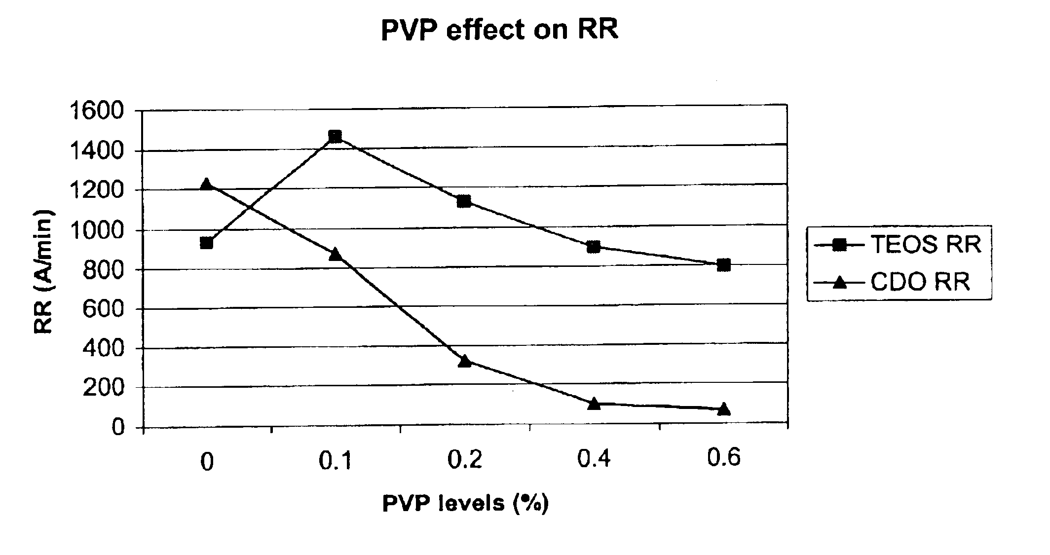
[0028]The following Table illustrates the impact on removal rates with a 3 psi (20.7 kPa) down force for various semiconductor constituents.

[0029]

TABLE 2SlurryPVP(%)TEOS RRCDO RRCu RRTaN RRA0933122787102010.11457867241142120.2129434770119040.4895100294104060.6795673241007RR = Removal Rate

[0030]The addition of PVP, as plotted in FIG. 1, shows that the CMP polishing process removes both TEOS (capping material) and low K materials (CDO) for slurries lacking PVP. But adding PVP to the slurry, however, allows the slurry to selectively remove TEOS film in relation to low-k films. Therefore, this formulation allows chip fabricators to provide chemical mechanical planarization and stop on a low-k film. For example, some dual hard mask / cap integration schemes will require removing a TEOS cap while stopping on a SiC or CDO layer. For these integration schemes, slurry 4 that has a high TEOS removal rate and stops on SiC provides an excellent solution.

example 2

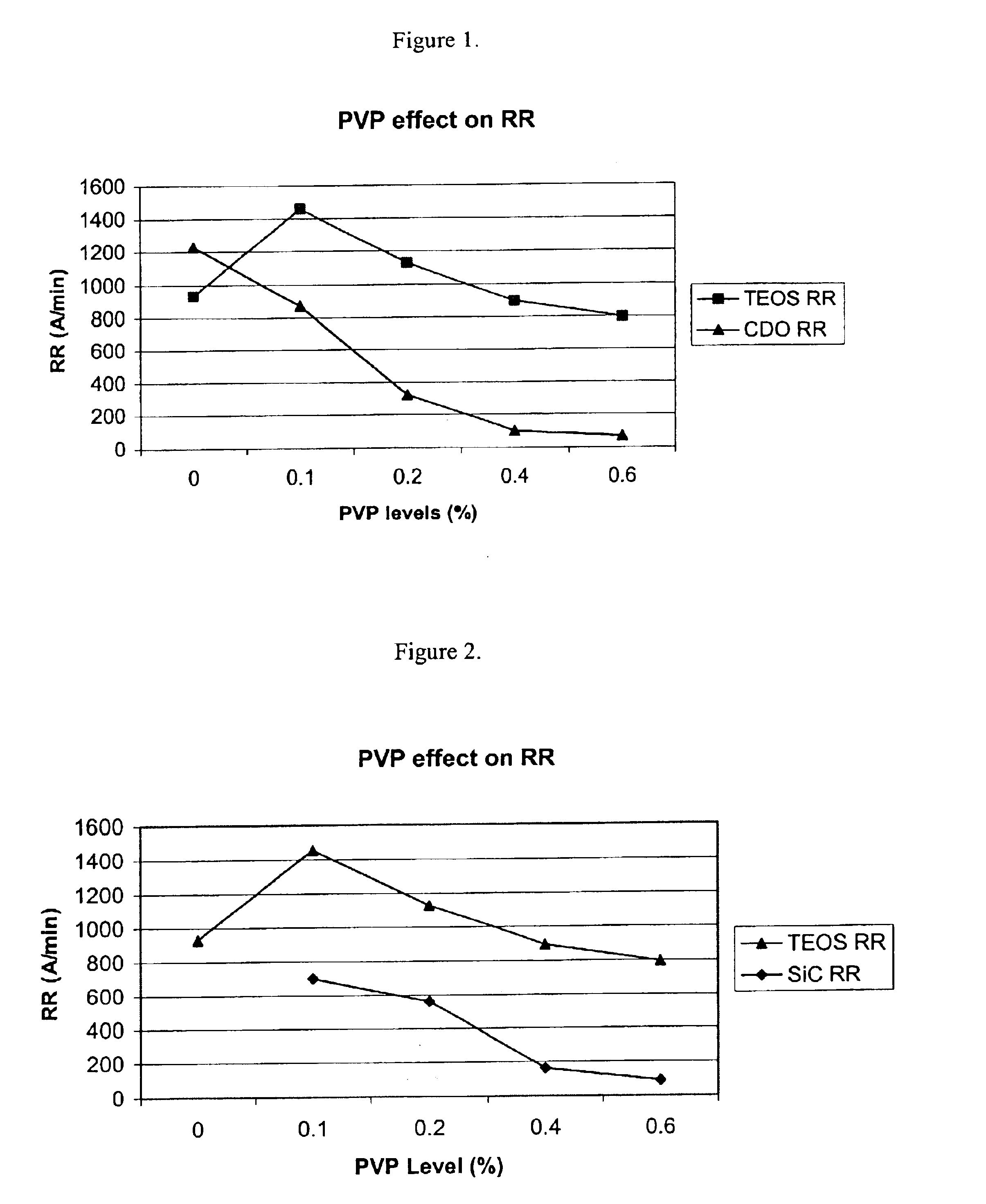
[0031]The following Table confirms the effects of PVP for SiC wafers and illustrates the effect arising from decreasing down force to 2 psi (13.8 kPa).

[0032]

TABLE 3SlurryPVP(%)TEOS RRSIC RR*TaN RRCDO RRA055155794583310.1738697123758520.2615393102526340.45021639966960.643890101740RR = Removal Rate

[0033]As observed in Example 1, CDO removal rate decreased with the increase of PVP in slurry. In addition to this, as illustrated in FIG. 2, the PVP addition also decreased the SiC removal rate. Because of the relative hardness of SiC to CDO, the SiC removal rate is typically much lower than the CDO removal rate for most polishing slurries. But the PVP-containing solutions showed generally higher SiC removal rates than CDO removal rates.

example 3

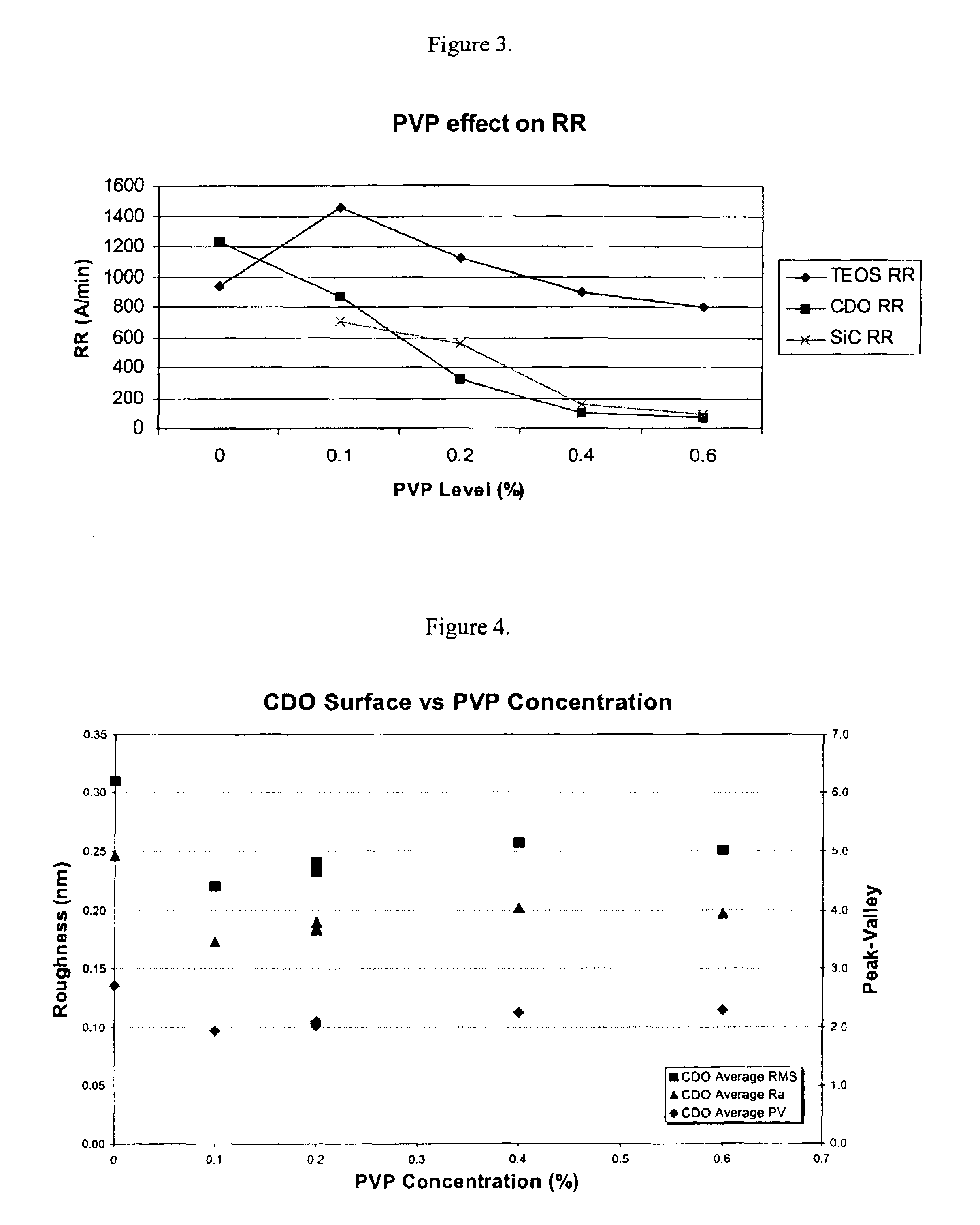
[0034]The following series evaluates the solid concentration effect for slurries having 8.5 weight percent silica on the SiC and CDO wafers with a 2 psi (13.8 kPa) down force.

[0035]

TABLE 4SlurryPVP(%)TEOS RRSIC RRTaN RRCDO RRB041038669457980.2375215902150110.62976280739RR = Removal Rate

[0036]As observed in the earlier Examples, PVP lowered the CDO and SiC removal rates. FIG. 3 illustrates the dramatic effect on low-k removal rates achieved for the slurries of Table 4.


PUM

PropertyMeasurementUnit
zeta potentialaaaaaaaaaa
particle sizeaaaaaaaaaa
pHaaaaaaaaaa

Abstract

An aqueous slurry is useful for chemical mechanical planarizing a semiconductor substrate. The slurry includes by weight percent, 0.1 to 25 oxidizing agent, 0.1 to 20 silica particles having an average particle size of less than 200 nm, 0.005 to 0.8 polyvinyl pyrrolidone for coating the silica particles, 0.01 to 10 inhibitor, 0.001 to 10 complexing agent and a balance water and incidental impurities; and the aqueous slurry having a pH of at least 7.

Description

BACKGROUND OF THE INVENTION[0001]The introduction of new low-k and ultra-low-k dielectrics into chip manufacturing poses new challenges for chemical mechanical planarization (CMP). Since the mechanical strength of low-k and ultra-low-k materials is relatively low, the mechanical force applied during CMP can fracture or delaminate low-k films from wafer substrates. Consequently, CMP is moving towards employing its polishing equipment with lower down forces, i.e. forces of or less than 3 psi (20.7 kPa). Operating the polishing equipment with lower down forces requires the polishing slurries to possess an increased removal rate to facilitate acceptable wafer throughput rates.[0002]Another challenge facing slurry manufacturers is that the current low-k / ultra-low-k integration architectures are extremely diverse and largely depend on user-specific targets. Some relatively simple integration schemes will use conventional CMP slurries that have a low selectivity to the dielectric material....

Claims


Application Information

Patent Timeline
Patent Type & Authority Patents(United States)
IPC IPC(8): C09G1/02C09G1/00H01L21/02H01L21/321H01L21/306H01L21/3105C09K3/14
CPCC09G1/02C09K3/1463H01L21/31053H01L21/3212B24D3/002C01B33/023H01L21/30625
Inventor YE, QIANQIUVANHANEHEM, MATTHEWQUANCI, JOHN
Owner ROHM & HAAS ELECTRONICS MATERIALS CMP HLDG INC
Why Eureka
Try Eureka