Vehicle collision severity estimation system

a collision severity and estimation system technology, applied in the direction of pedestrian/occupant safety arrangement, using reradiation, instruments, etc., can solve the problems of reducing the probability of the energy imparted in a potential collision or injury, the difficulty of obtaining velocity and mass determination of the target object, and the inability to measure the state and characteristics of the measured object, so as to reduce image processing time, the effect of system versatility and performance capability

Inactive Publication Date: 2005-07-12
FORD GLOBAL TECH LLC
View PDF11 Cites 28 Cited by
  • Summary
  • Abstract
  • Description
  • Claims
  • Application Information

AI Technical Summary

Benefits of technology

[0011]Another advantage of the present invention is system versatility and performance capability, through the use of one or more object detection sensors of various type and style. The combination of multiple sensor types reduces image-processing time and increases the number and accuracy of the measured object states and characteristics. This in turn increases measurement quality, which corresponds to better object classification and mass prediction.
[0012]The present invention itself, together with attendant advantages, will be best understood by reference to the following detailed description, taken in conjunction with the accompanying figures.

Problems solved by technology

Collision warning systems and countermeasure systems can decrease the probability of and the energy imparted in a potential collision or injury.
On the other hand velocity and mass determination of the target object is more difficult to obtain.
Current active electro-magnetic wave ranging devices such as radar and lidar are capable of measuring velocity, but are incapable of measuring mass of the target object.

Method used


Image

  • Vehicle collision severity estimation system
  • Vehicle collision severity estimation system
  • Vehicle collision severity estimation system

Examples


Embodiment Construction

[0017]While the present invention is described with respect to a method and system for estimating collision severity between a host vehicle and a target object during assessment of a potential collision, the present invention may be adapted to be used in various systems including: automotive vehicle systems, control systems, hybrid-electric vehicle systems, or other applications utilizing active or passive countermeasure devices.

[0018]In the following description, various operating parameters and components are described for one constructed embodiment. These specific parameters and components are included as examples and are not meant to be limiting.

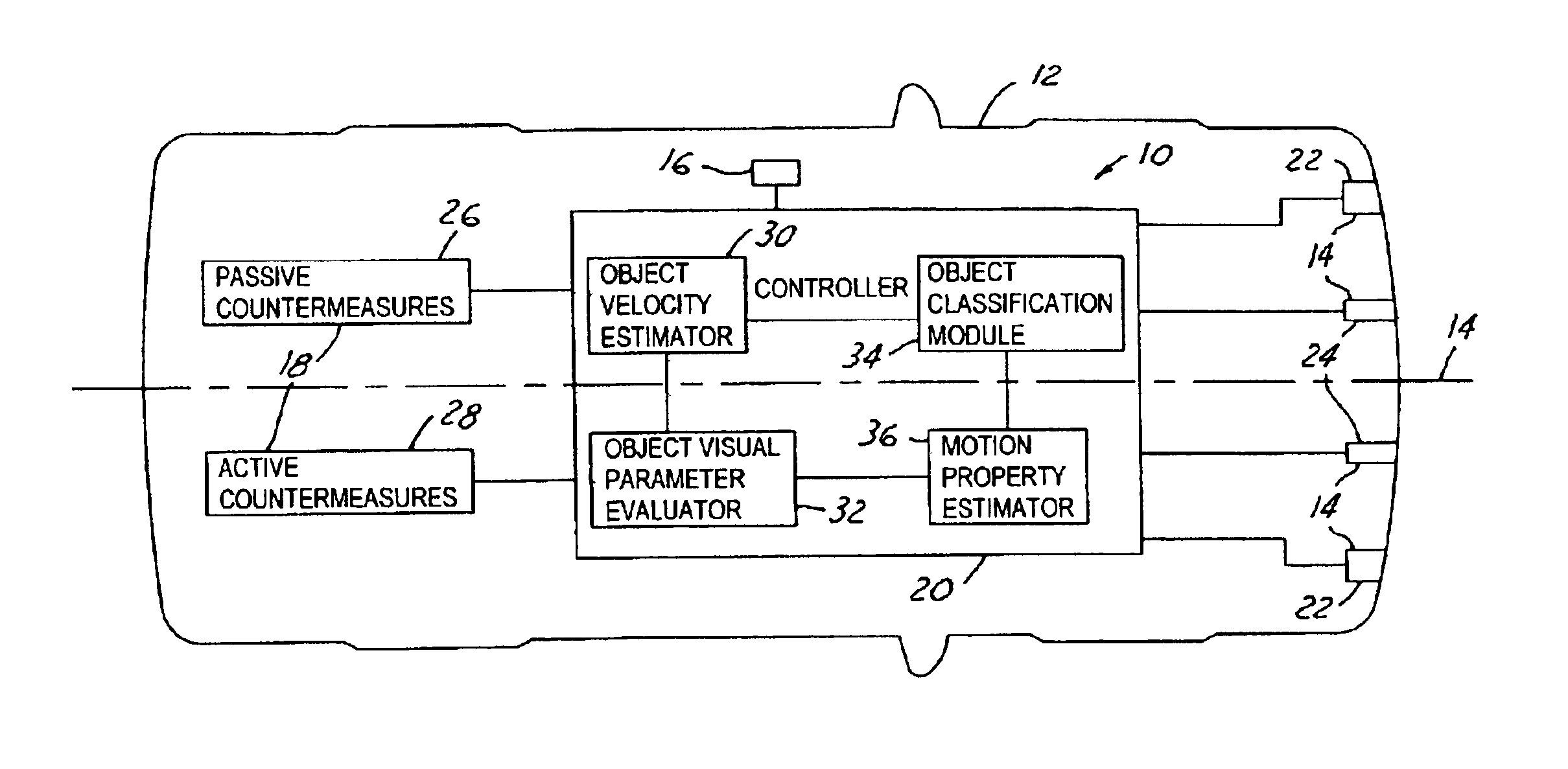
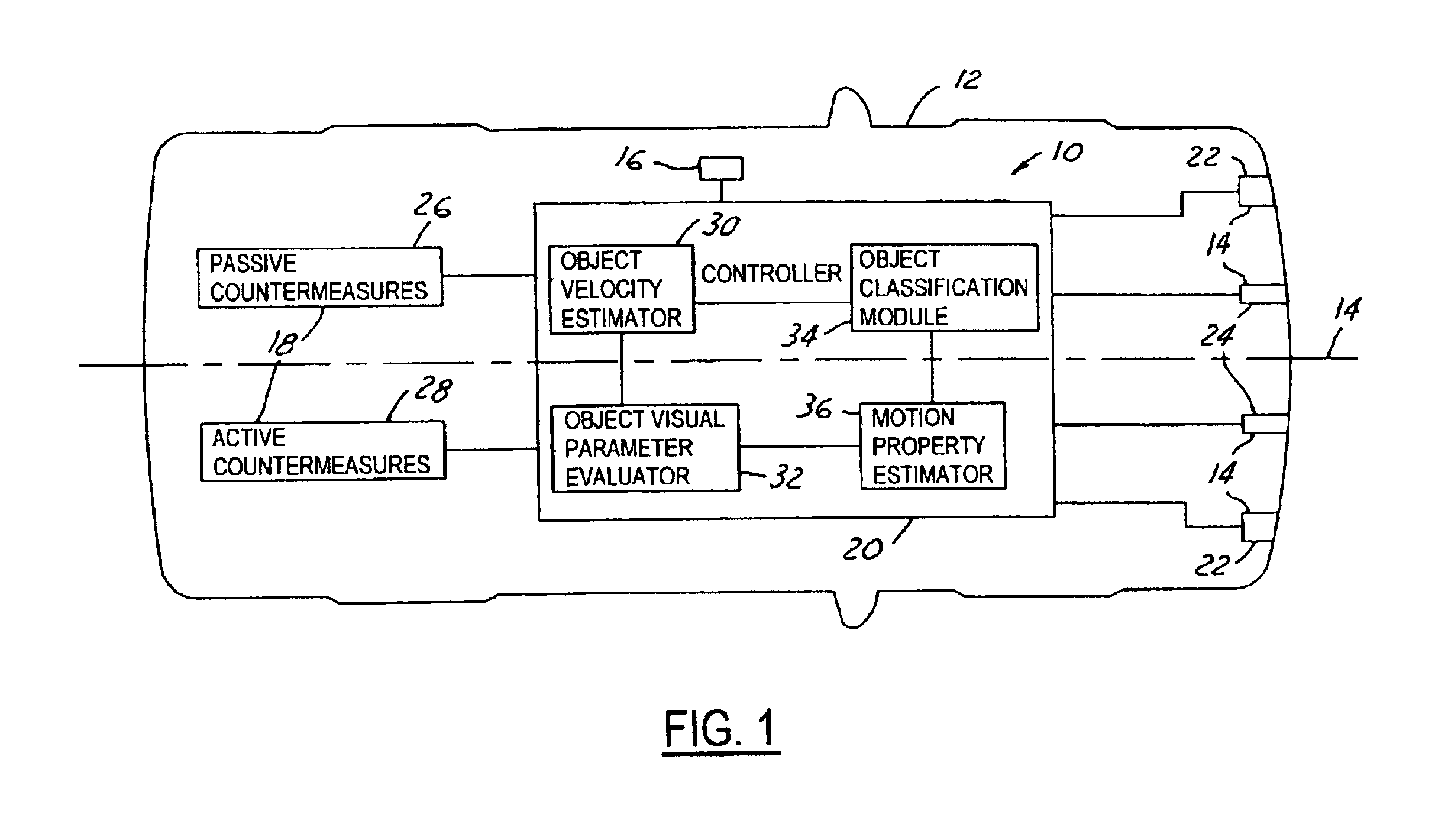
[0019]Referring now to FIG. 1, a block diagrammatic view of a vehicle collision severity estimation system 10 for an automotive vehicle 12 in accordance with an embodiment of the present invention is shown. The system 10 includes one or more object detection sensors 14. The object detection sensors 14 as well as a host vehicle velocity s...


PUM


Abstract

A collision severity estimation system (10) for an automotive vehicle (12) is provided. The system (10) includes one or more object detection sensors (22) detecting an object and generating a first object detection signal. A controller (20) is electrically coupled to the object detection sensors (22) and determines motion properties of the object relative to the vehicle (12) and generates an object motion signal in response to the first object detection signal. The controller (20) determines potential collision severity between the vehicle (12) and the object in response to the object motion signal and generates a collision severity signal. Methods of determining motion properties of the object as well as determining potential collision severity between the vehicle (12) and the object are also provided.

Description

BACKGROUND OF INVENTION[0001]The present invention relates generally to collision mitigation and avoidance systems for automotive vehicles, and more particularly, to a method and system for estimating collision severity between a host vehicle and an impending target object during assessment of a potential collision event.[0002]Collision warning and countermeasure systems are becoming more widely used. Collision warning systems and countermeasure systems can decrease the probability of and the energy imparted in a potential collision or injury. Collision warning systems provide a vehicle operator increased knowledge and awareness of threatening objects or vehicles within a close proximity so as to reduce the probability of colliding with those objects. Countermeasure systems exist in various passive and active forms. Some countermeasure systems are used to potentially decrease the energy of a collision, while others are used to aid in the prevention and reduction of injury to a vehic...

Claims


Application Information

Patent Timeline
Patent Type & Authority Patents(United States)
IPC IPC(8): B60R21/01G01S13/93G01S13/00G01S7/02G01S7/41G08G1/16B60R21/0134B60R21/015B60W30/08B60W50/00B60W50/02G01S13/931
CPCB60R21/013B60R21/01558B60W30/08G01S7/412G01S13/931G08G1/16B60T2201/02B60W30/09B60W50/02B60W50/14B60W2050/0028B60W2550/20B60W2750/30G01S2013/9339G01S2013/9353B60R21/0134G08G1/166G01S2013/9329G01S2013/932B60W2754/10B60W2554/00B60W2554/80B60W2554/20
Inventor KING, ANTHONY GERALD
Owner FORD GLOBAL TECH LLC
Why Eureka
Try Eureka