
Light diffusion film, plane light source device and liquid crystal display apparatus for enhancing a constant luminance and diffusing a light

a technology of liquid crystal display and diffusion film, which is applied in the direction of planar/plate-like light guides, instruments, transportation and packaging, etc., can solve the problems of further driving up the cost of assembling, increasing the defective fraction, and driving up the cost of raw materials and assembling. , to achieve the effect of reducing the cos

Inactive Publication Date: 2005-07-12
DAICEL CHEM IND LTD
View PDF36 Cites 85 Cited by
  • Summary
  • Abstract
  • Description
  • Claims
  • Application Information

AI Technical Summary

Benefits of technology

[0021]The inventors of the present invention did much research to accomplish the above objects and found that: in a plane light source unit comprising a wedge-shaped reflecting groove formed at the bottom of a light guide, use of a light-diffusing film having appropriate anisotropy (anisotropic property) and scattering property (haze) realizes a plane light source device in which deterioration of the luminance is inhibited and TCO standard is accepted. Moreover, the inventors of the present invention found that: by disposing a film having light-scattering property and ultraviolet absorbability on a light-emitting surface of a plane light source unit, leakage of an ultraviolet ray is extremely inhibited at a lower cost with reliability and certainty over the long term, and various constituent members (such as a plane light source device and a liquid crystal cell) are effectively protected from leaked ultraviolet ray, as a result deterioration of functions of a liquid crystal display apparatus is inhibited. The present invention has been developed on the basis of the above findings.
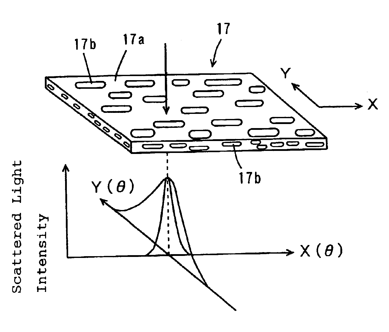
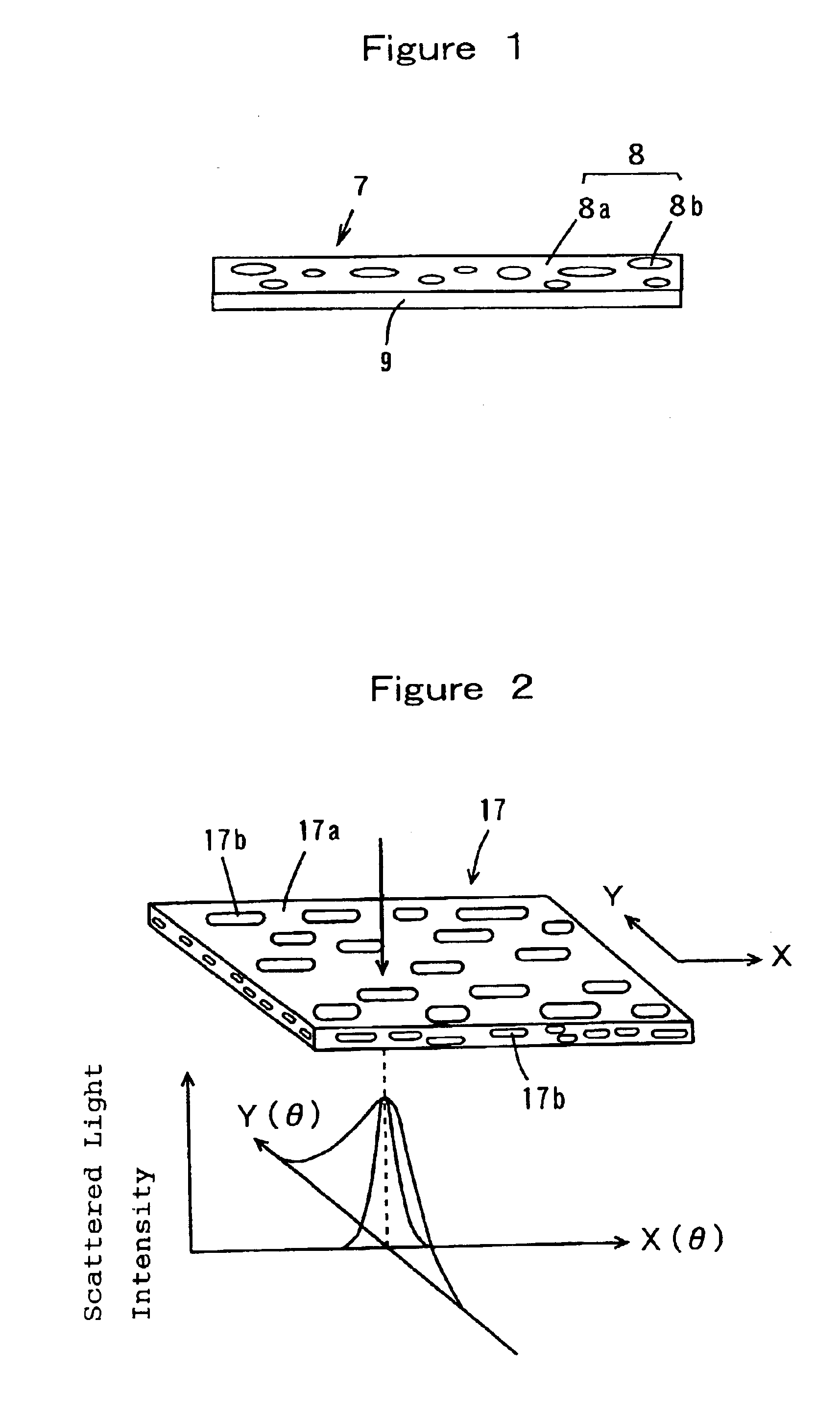
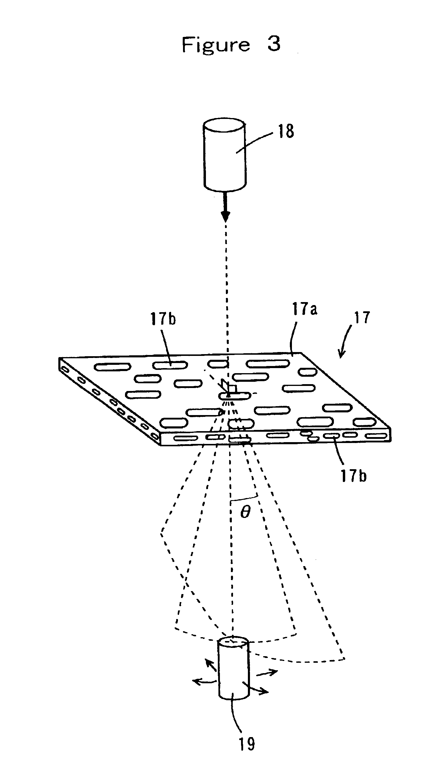
[0023]wherein Fx(θ) represents a light-scattering characteristic in an X-axial direction of the film and Fy(θ) represents a light-scattering characteristic in a Y-axial direction of the film. Moreover, the light-scattering characteristics Fx(θ) and Fy(θ) of the anisotropic light-diffusing film may fulfill 1.01≦Fy(θ) / Fx(θ)≦100, or may fulfill Fy(θ) / Fx(θ)≧1.1 (for example, 1.1≦Fy(θ) / Fx(θ)≦500), over a range of θ=4 to 30°. Further, the light-diffusing film has a light-scattering characteristics Fx(θ) and Fy(θ) fulfilling the expression 1.1≦Fy(θ) / Fx(θ)≦20 in a scattering angle of θ=18°. The light-scattering characteristics may fulfill the following expressions: 1.01≦Fy(θ) / Fx(θ)≦20 (θ=4 to 30°) and 1.1≦Fy(θ) / Fx(θ)≦10 (θ=18°). Such a light-diffusing film may have ultraviolet absorbability. Use of the light-diffusing film fulfilling the above-mentioned light-scattering characteristics realizes high uniformity of the luminance in the display surface which is observed from a wide angle in a direction such as the horizontal direction and the vertical direction.
[0025]Moreover, the present invention also includes a light-diffusing film for disposing on a light-emitting side of a plane light source unit, wherein the film has ultraviolet absorbability for absorbing an ultraviolet ray leaked from the plane light source unit. The light-diffusing film may be an isotropic diffusing film in which an incident light is diffused isotropically, or may be an anisotropic diffusing film in which an incident light is diffused anisotropically. That is, the light-diffusing film may show an anisotropy in light scatteration (or an anisotropic light scatteration). Use of such a film realizes uniformity of the luminance in the display surface which is observed even from a wide angle in a direction such as the horizontal direction and the vertical direction in a plane light source device. For example, a light-scattering characteristic F(θ) representing the relationship between a light-scattering angle θ and a scattered light intensity F may fulfill the above-mentioned light-scattering characteristics, for example, Fy(θ) / Fx(θ)≧1.01 (preferably Fy(θ) / Fx(θ)≧1.1, e.g., 1.1≦Fy(θ) / Fx(θ)≦500) over a range of θ=4 to 30°, wherein Fx(θ) represents the light-scattering characteristic in an X-axial direction of the film and Fy(θ) represents the light-scattering characteristic in a Y-axial direction of the film. Moreover, the scattering characteristic Fx(θ) and scattering characteristic Fy(θ) may fulfill the following expression, 1.1≦Fy(θ) / Fx(θ)≦20 at θ=18°. Such an anisotropic light-diffusing film apparently ensures uniformity of the luminance in a direction such as the horizontal direction and the vertical direction.
[0026]The light-diffusing film need only comprise at least a light-diffusing layer, and may be formed with a monolayer structure, or a laminated structure (laminator), for example, a laminated structure comprising a light-diffusing layer composed of a plurality of resins which are different from each other in refractive index, and a transparent layer laminated on at least one side of the light-diffusing layer. In a light-diffusing film having ultraviolet absorbability, an ultraviolet absorber may be included in the light-diffusing layer and / or the transparent layer, and is usually included in at least the transparent layer. Among such laminated films, arrangement of the transparent layer on a light-emitting surface of a plane light source unit realizes effective protection of the light-diffusing layer and more stable inhibition of ultraviolet leakage.

Problems solved by technology

However, in the plane light source device employing a fluorescent discharge tube, a light guide, a diffusing plate, a prism sheet (further if necessary, a protecting film for the prism sheet) as described above, costs for raw materials and for assembling are driven up due to a large number of components, and the defective fraction is increased because exogenous materials are apt to enter between components.
Incidentally, it is also considered to remove the exogenous materials, but costs for assembling are further driven up.
However, the light is scattered by a scattering dot of the light guide or a diffusing sheet at a large scattering angle, and the light cannot be focused with the use of a prism sheet.
It is, therefore, impossible to uniformly illuminate the intra-surface of the plane light source unit and forming a uniform plane light source is difficult.
However, in the case where the diffusing sheet is disposed, the luminance is extremely deteriorated, and TCO standard (The Swedish Confederation of Professional employee) which limits change of the luminance, when the display member is observed from an oblique direction, is unsatisfied.
Further, in a conventional liquid crystal display apparatus, an ultraviolet ray (light) leaks out from a tubular light source such as a fluorescent tube, and constituent members of the plane light source unit (for example, the diffusing sheet, the prism sheet, the sheet for improving luminance (a reflective polarizing plate, etc.), the polarizing plate, the phase plate, the liquid crystalline material and the color filter) are deteriorated in long-standing use.
However, in the former method, it is necessary to use a high heat-resistant film, and in the latter method, the color (hue) changes over the whole apparatus because the ultraviolet absorber slightly absorbs visible lights.
However, even in such a method, an ultraviolet ray leaks from a backlight unit.
In particular, in a backlight having a wedge-shaped reflecting groove formed at the bottom of a light guide, a strong ultraviolet ray leaks from the light guide because the white scatterer composed of the fluorescent material is not employed.

Method used


Image

  • Light diffusion film, plane light source device and liquid crystal display apparatus for enhancing a constant luminance and diffusing a light
  • Light diffusion film, plane light source device and liquid crystal display apparatus for enhancing a constant luminance and diffusing a light
  • Light diffusion film, plane light source device and liquid crystal display apparatus for enhancing a constant luminance and diffusing a light

Examples


example 1

[0163]The following resins were used: 90 parts by weight of a crystalline polypropylene-series resin PP (manufactured by Grand Polymer Co., F133, refractive index: 1.503) as the continuous phase resin; 9.5 parts by weight of a polystyrenic resin GPPS (general purpose polystyrenic resin, manufactured by Daicel Chemical Industries, Ltd., GPPS#30, refractive index: 1.589) as the dispersed phase resin; and 0.5 part by weight of an epoxidized diene-series block copolymer resin (manufactured by Daicel Chemical Industries, Ltd., Epofriend AT202; styrene / butadiene=70 / 30 (by weight), epoxy equivalent: 750, refractive index: about 1.57) as the compatibilizing agent.

[0164]The above continuous phase resin and dispersed phase resin were dried at 70° C. for about 4 hours, and these resins and the compatibilizing agent were kneaded in a Banbury mixer. Using an extruder, the resultant was melted at about 220° C. and extruded from a T-die with a draw ratio of about 3 onto a cooling or chilling drum ...

example 2

[0166]As components for the light-diffusing layer were used 85 parts by weight of a crystalline polypropylene-series resin PP (manufactured by Grand Polymer Co., F133, refractive index: 1.503) as the continuous phase resin; 14.5 parts by weight of a polystyrenic resin GPPS (general purpose polystyrenic resin, manufactured by Daicel Chemical Industries, Ltd., GPPS#30, refractive index: 1.589) as the dispersed phase resin; and 0.5 part by weight of an epoxidized diene-series block copolymer resin (manufactured by Daicel Chemical Industries, Ltd., Epofriend AT202; styrene / butadiene=70 / 30 (by weight), epoxy equivalent: 750, refractive index: about 1.57) as the compatibilizing agent. As a component for the transparent resin layer, the above crystalline polypropylene-series resin PP was used.

[0167]The above components for the light-diffusing layer and the component for the transparent resin layer were each dried at 70° C. for about 4 hours, and the components for the light-diffusing layer...

example 3

[0169]A film was produced in the same manner as in Example 2 except that a noncrystalline copolyester-series resin was used instead of the dispersed phase resin. That is, the following resins were used: 80 parts by weight of a crystalline polypropylene-series resin PP (manufactured by Grand Polymer Co., F133, refractive index: 1.503) as the continuous phase resin; 19 parts by weight of a noncrystalline copolyester-series resin (PET-G, manufactured by Eastman Chemical Company, Eastar PETG GN071, refractive index: 1.567) as the dispersed phase resin; and 1 part by weight of an epoxidized diene-series block copolymer resin (manufactured by Daicel Chemical Industries, Ltd.; Epofriend AT202; styrene / butadiene=70 / 30 (by weight), epoxy equivalent: 750, refractive index: about 1.57) as the compatibilizing agent. For the surface layer (transparent resin layer), the same resin as the above continuous phase resin was employed.

[0170]As with Example 2, using an extruder of multi-layered type, th...


PUM

PropertyMeasurementUnit
mean sizeaaaaaaaaaa
mean aspect ratioaaaaaaaaaa
refractive indexaaaaaaaaaa

Abstract

A transmissive display apparatus comprises a liquid crystal display unit; and a plane light source unit that comprises a tubular light source, a light guide, and a light-diffusing film having anisotropy that provides a consistent luminance in a display surface, and / or ultraviolet (UV) absorbability that absorbs the UV from the light source and prevents deterioration of a prism sheet in the display unit and liquid display cell. In the film, a light-scattering characteristic F(θ) represents a relationship between the light-scattering angle θ and a scattered light intensity F fulfills Fy(θ) / Fx(θ)≧1.01 over a range of θ=4 to 30°, wherein Fx(θ) and Fy(θ) represent the light-scattering characteristics in an X-axial direction and Y-axial direction of the film, respectively. The film comprises a light-diffusing layer composed of a plurality of resins which are different from each other in refractive index, and a transparent layer laminated on at least one side thereof.

Description

[0001]This application is the national phase under 35 U.S.C. § 371 of PCT International Application No. PCT / JP02 / 05313 which has an International filing date of May 30, 2002, which designated the United States of America.TECHNICAL FIELD[0002]The present invention relates to a light-diffusing film useful for diffusing a light ray, a plane light source device and a liquid crystal display apparatus using the same.BACKGROUND ART[0003]In a backlight type display apparatus (a liquid crystal display apparatus) illuminating a display panel (e.g., a liquid crystal display module) from its backside, a plane or flat light source unit (or a backlight unit) is disposed on the backside of the display panel. Moreover, a diffusing sheet, a prism sheet, a sheet for improving luminance (a reflective polarizing plate, etc) or the like is employed in order to uniformize an illuminating light (illuminating radiation) on a display panel for using it as a plane or flat light source and to enhance the lumi...

Claims


Application Information

Patent Timeline
Patent Type & Authority Patents(United States)
IPC IPC(8): F21V8/00G02B5/02
CPCG02B5/0242G02B5/0257G02B5/0278G02B6/0056G02B6/0065G02B6/004Y10T428/10C09K2323/00G02F1/1335
Inventor HIRAISHI, MASANORIOHNISHI, MASANARISASAGAWA, TOMOHIROIWASAKI, NAOKOYUUKI, AKIMASAMURAKAMI, OSAMU
Owner DAICEL CHEM IND LTD
Learn More