Optical bodies containing cholesteric liquid crystal material and methods of manufacture

a technology of optical bodies and liquid crystal materials, applied in the direction of instruments, polarising elements, chemistry apparatus and processes, etc., can solve the problems of low transmission or reflectance of these displays, reducing display contrast and brightness, and requiring high power consumption, so as to hinder the diffusion of cholesteric liquid crystal materials

Inactive Publication Date: 2005-07-12
3M INNOVATIVE PROPERTIES CO
View PDF112 Cites 62 Cited by
  • Summary
  • Abstract
  • Description
  • Claims
  • Application Information

AI Technical Summary

Benefits of technology

[0010]Another embodiment of the invention is an optical body which comprises a substrate and a cholesteric liquid crystal layer disposed on the substrate. The cholesteric liquid crystal layer has a non-uniform pitch along a thickness direction of the layer and comprises a crosslinked polymer material that substantially fixes the cholesteric liquid crystal layer. The crosslinking hinders diffusion of cholesteric liquid crystal material within the cholesteric liquid crystal layer.
[0011]Another embodiment of the invention is an optical display which comprises a display medium and a reflective polarizer. The reflective polarizer comprises a substrate and a cholesteric liquid crystal layer disposed on the substrate. The cholesteric liquid crystal layer has a non-uniform pitch along a thickness direction of the layer and comprises a crosslinked polymer material that substantially fixes the cholesteric liquid crystal layer. The crosslinking hinders diffusion of cholesteric liquid crystal material within the cholesteric liquid crystal layer.

Problems solved by technology

The low transmission or reflectance of these displays reduces display contrast and brightness and can require high power consumption.

Method used


Image

  • Optical bodies containing cholesteric liquid crystal material and methods of manufacture
  • Optical bodies containing cholesteric liquid crystal material and methods of manufacture
  • Optical bodies containing cholesteric liquid crystal material and methods of manufacture

Examples


example 1

[0082]Different coating solutions were prepared for the coating procedure. The composition of these coating solutions is listed in Table 1. Coating solution 4 is a mixture of solutions 1 and 2. Tetrahydrofuran (THF) and methyl ethyl ketone (MEK) (both available from Aldrich Chemical Co., Milwaukee, Wis.) were used as the solvents. The preparation of Compound A is described in European Patent Application Publication No. 834754, which is incorporated herein by reference. The structure of Compound A is:

Compound 756 (Paliocolor™ LC756) and Compound 242 (Paliocolor™ LC242) are liquid crystal monomers available from BASF Corp. (Ludwigshafen, Germany). Darocurm ™ 4265 (Ciba Geigy Corp., Basel, Switzerland) is a photoinitiator. Vazo™ 52 (DuPont, Wilmington, Del.) is a thermally decomposable substituted azonitrile compound used as a free radical initiator. The substrate used for coating had an alignment layer on it consisting of stretched (by a factor of 6.8) polyvinyl alcohol (PVA) (Airvol...

example 2

[0087]Coating solution 5 was prepared by dissolving the compounds of coating solution 5, as listed in Table 1, in THF at 60° C. Coating solution 5 was then purged with nitrogen gas, sealed in a container, and heated at 60° C. for 16 hours in order for polymerization of the liquid crystal monomer to occur. Coating solutions 6 and 7 were prepared by dissolving the indicated compounds in the solvents at 60° C. Coating solution 10 was prepared by mixing solutions 5 and 6, and then adding Lucirin™ TPO (BASF Corp., Ludwigshafen, Germany), at room temperature.

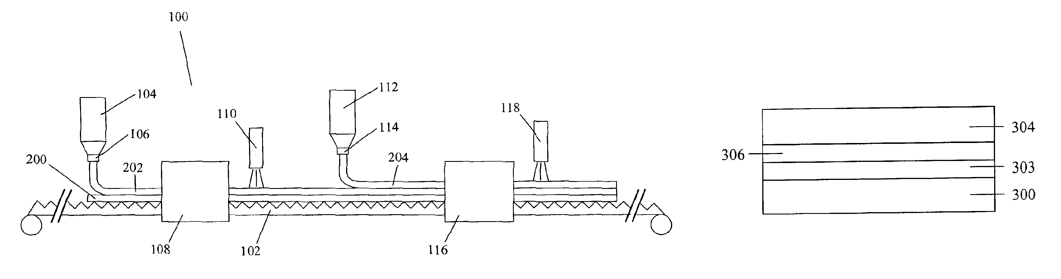
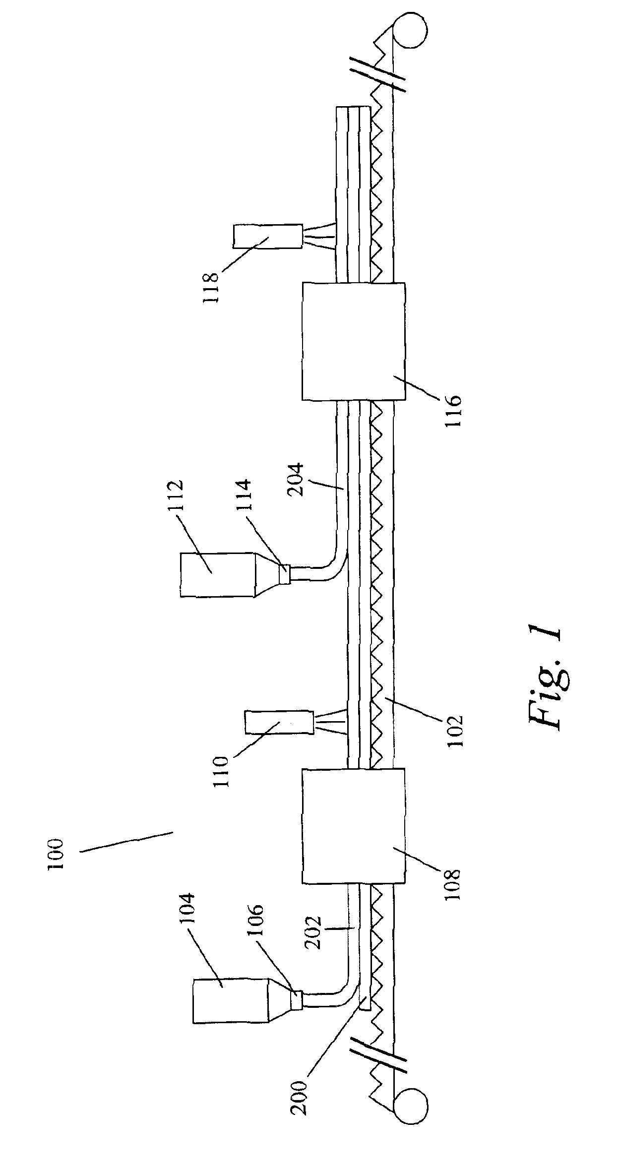
[0088]An optical body was prepared by applying coating solution 10 on the PVA substrate using a #26 wire wrapped rod. Coating solution 10 was applied to give a thickness, when dried, of approximately 10 micrometers. The coating was air dried for 5 minutes at room temperature and then placed into a 115° C. oven for 10 minutes to align the polymer. Next, the coating was UV cured in air using a 300 watt / in. Fusion™ conveyor UV curing sys...

example 3

[0091]Coating solution 8 was prepared by dissolving the compounds of coating solution 8, as listed in Table 1, in THF at 60° C. Coating solution 8 was then purged with nitrogen gas, sealed in a container, and heated at 60° C. for 16 hours in order for polymerization of the liquid crystal monomer to occur. Coating solutions 9 and 12 were prepared by dissolving the indicated compounds in the solvents at 60° C. Coating solution 11 was prepared by mixing solutions 8 and 9, and then adding the photoinitiator at room temperature.

[0092]The optical body was prepared by applying coating solution 11 on the PVA substrate using a #20 wire wrapped rod. Coating solution 11 was applied to give a thickness, when dried, of approximately 7.5 micrometers. The coating was air dried for 5 minutes at room temperature and then placed into a 120° C. oven for 10 minutes to align the polymer. Next, the coating was UV cured in air using a 300 watt / in. Fusion™ conveyor UV curing system (Fusion MC-6RQN) and a F...


PUM

PropertyMeasurementUnit
reflectivityaaaaaaaaaa
distanceaaaaaaaaaa
wavelength rangeaaaaaaaaaa

Abstract

An optical body includes a substrate and a cholesteric liquid crystal layer disposed on the substrate. The cholesteric liquid crystal layer has a non-uniform pitch along a thickness direction of the layer and comprises a crosslinked polymer material that substantially fixes the cholesteric liquid crystal layer. The crosslinking hinders diffusion of cholesteric liquid crystal material within the cholesteric liquid crystal layer. In other methods of making an optical body, a reservoir of chiral material is provided during the process over a first cholesteric liquid crystal layer to diffuse into the layer and provide a non-uniform pitch. Alternatively, two coating compositions can be disposed on a substrate where the material of the first coating composition is not substantially soluble in the second coating composition.

Description

FIELD OF THE INVENTION[0001]The present invention relates to optical bodies containing cholesteric liquid crystals. The present invention also relates to reflective optical polarizers formed by coating of two or more layers of cholesteric liquid crystals or cholesteric liquid crystal precursors.BACKGROUND OF THE INVENTION[0002]Optical devices, such as polarizers and mirrors, are useful in a variety of applications including liquid crystal displays (LCD's). Liquid crystal displays fall broadly into two categories: backlit (e.g., transmissive) displays, where light is provided from behind the display panel, and frontlit (e.g., reflective) displays, where light is provided from the front of the display (e.g., ambient light). These two display modes can be combined to form transflective displays that can be backlit, for example, under dim light conditions or read under bright ambient light.[0003]Conventional backlit LCDs typically use absorbing polarizers and can have less than 10% ligh...

Claims


Application Information

Patent Timeline
Patent Type & Authority Patents(United States)
IPC IPC(8): G02B5/30G02F1/1335
CPCG02B5/3016G02F1/1335
Inventor POKORNY, RICHARD JOHNRADCLIFFE, MARC DUDLEYWATSON, PHILIP EDWINBOWLEY, CHRISTOPHER CHADWICKEBIHARA, IKUKO
Owner 3M INNOVATIVE PROPERTIES CO
Why Eureka
Try Eureka