Superheater capillary two-phase thermodynamic power conversion cycle system

a two-phase thermodynamic power conversion and superheater technology, applied in steam superheaters, steam engine plants, lighting and heating apparatus, etc., can solve the problems of inability to use rankine power cycles in space applications, inability to achieve infinitesimally small changes in flow quality, and inability to achieve the effect of large-scale operation, improved efficiency, and effective separation

Inactive Publication Date: 2005-07-19
THE AEROSPACE CORPORATION
View PDF8 Cites 53 Cited by
  • Summary
  • Abstract
  • Description
  • Claims
  • Application Information

AI Technical Summary

Benefits of technology

[0014]Yet, another object of the invention is to provide a two-phase thermal cycle for use in a thermodynamic power system pressurized by a capillary device, superheater and liquid pump for generating power at high efficiencies while operating at low temperatures.
[0022]Still a further object of the invention is to provide a two-phase thermal cycle for use in a thermodynamic power system pressurized by a capillary device for generating power during power generation with improved efficiency using an in-line superheater, a preheater, and a liquid pump.
[0023]The system is directed to a two-phase thermodynamic power cycle system that converts heat energy to work particularly useful in space power systems. The system uses a capillary wick of a capillary device that uses input heat to generate high-pressure saturated vapor. The high-pressure saturated vapor is kept separate from low-pressure saturated liquid. This capillary wick facilitates the flow transition from high pressure, high temperature, saturated liquid to high-pressure, saturated vapor, instantaneously, providing effective separation between liquid and vapor and being a passive pump. The system solves the problem of two-phase fluid management in micro gravity by simplifying the two-phase thermodynamic cycle system using a capillary device, such as loop heat pipe or a capillary pumped loop, for two-phase fluid control. The system is a power conversion unit that receives heat from a heat source to passively drive the capillary action. The capillary action passively separates liquid from vapor and pressurizes the flow so that high-pressure saturated vapor can enter the superheater of the system. Saturated high-pressure vapor flows into the superheater through diode valves. These valves allow the flow to enter the superheater but prevent the flow from flowing back towards the evaporator. Once the pressure in the superheater equals the pressure of the high pressure, saturated vapor, flow into the superheater stops. Heat addition to the high-pressure, saturated vapor continues until the vapor reaches the desired superheated vapor state. Once the vapor reached the desired state of superheat, the superheater control valve is opened releasing superheated vapor that flows to the turbine. Vapor flows isentropically through the turbine where work is taken out of the flow. Multiple superheater stages can be used. The pulsing of these multiple stages can be staggered in order to obtain a flow that is steadier than simple pulses. The superheater can be one leg or several parallel tube legs, for example each leg tens of feet long, bent in a serpentine manner, attached to a heat source. Each leg of the superheater has a controllable diode input valve and controllable exit valve. The flow exits the turbine as low-pressure, saturated vapor and enters the condenser. The vapor condenses in the condenser and leaves as low pressure saturated liquid. The condenser can be one tube, for example, tens of feet long, bent in a serpentine manner, and attached to a condenser panel. The condenser tubing can also be fabricated in a conventional parallel arrangement. Liquid enters a pump where work is put in and the liquid is pressurized isentropically to a high pressure, low temperature, subcooled liquid. The high pressure, low temperature, subcooled liquid flows through the liquid preheater and leaves as a high pressure, high temperature, saturated liquid which enters the evaporator to repeat the cycle. The liquid preheater can be one tube, for example, tens of feet long, bent in a serpentine manner, and attached to a heat source. The preheater tubing can also be fabricated in a conventional parallel arrangement.
[0024]The system preferably includes an evaporator comprising a capillary device having a capillary wick for receiving input heat and providing a phase change, a vapor accumulator to dampen and prevent mass flow oscillations from effecting the operation of the evaporator, a superheater receiving input heat and providing further increased pressure and temperature to the high pressure saturated vapor, a turbine for providing power, a condenser for radiating heat, a liquid pump for increasing the pressure of the low pressure saturated liquid and a preheater for increasing the temperature of the high pressure, low temperature, subcooled liquid.
[0026]The system preferably uses spacecraft thermal control technology, including loop heat pipes and capillary pumped loops, by combining these capillary devices with a turbine, superheater, liquid pump and liquid preheater. Loop heat pipes and capillary pumped loops are used for thermal control applications on spacecraft for a variety of reasons including that these devices allow for system integration with flexible lines, and enable deployable condensers. The system provides a two-phase dynamic power system suitable for space application. The system can be cost efficiently built as a system to generate power using the waste heat as a portion or all of the input heat from a spacecraft or waste heat from another dynamic or static power converters in a cascaded manner. This waste heat or cascaded system will yield a space power system with an overall efficiency of well over thirty percent to provide a spacecraft with significantly more power while enabling ion propulsion and increased payload capabilities.
[0028]The superheater is used to significantly increase the pressure of the vapor by adding additional heat bringing it to a superheated state. Although the vapor flow from the evaporator flows through the accumulator into the superheater, the evaporator is not exposed to the high pressures generated in the superheater. This is accomplished by pulsing the superheater using controllable diode and control valves. This allows for significantly higher-pressure, superheated vapor to flow into the turbine for power generation. This also insures that the working fluid flowing into the turbine is all vapor. In the preferred form of the invention, the superheater, disposed after the capillary wick and accumulator, is connected to a higher temperature heat source compared to the evaporator and liquid preheater heat sources. The superheater used in combination with a preheater and with a liquid pump that are both disposed before and the capillary wick allow for improved efficiency by increasing the operating range of the system. The flow is high-pressure saturated vapor that flows into the superheater. The superheater is preferably a heat exchanger that must interface with a heat source that is maintained at a higher temperature than the capillary wick. In practice, the superheater is a plurality of heat exchanging tubular chambers through which the cycle working fluid flows and is heated. Flow at the entrance to these chambers is checked by a diode valve, only allowing flow in. The exit to these chambers is checked by a control valve, operated so that the chamber pulses. This heat chamber can be attached to an external heat source. The flow is then heated for staggered release. Using multiple chambers, a quasi-continuous superheated vapor flow can be achieved for driving the turbine. The superheater is used to increase the efficiency of the cycle and to heat the working fluid to ensure that no condensed droplets enter the turbine. The impingement of droplets on the turbine will eventually cause the turbine to erode. The superheated vapor is passed through the turbine. Thermal energy storage material such as a phase change material can be connected to the superheater to store energy so that the superheater can operate constantly even if the heat source is not steady such as solar heating in Low Earth Orbit. This thermal energy storage material can be a single phase metal such as beryllium, or a two phase such as lithium or a molten salt that changes phase at the superheater operating temperature.

Problems solved by technology

Space power systems that do not generate AC power disadvantageously may require the use of an additional power converter, such as in photovoltaic and thermoelectric systems.
Space based dynamic power conversion cycles have been limited to single-phase Brayton and Stirling systems.
Although the Rankine cycle has been used extensively in terrestrial applications for power generation, the Rankine power cycle has not been used in space applications because of the difficulty and complexity required to manage a two-phase power system fluid in micro gravity.
The heating in the boiler of a Rankine cycle system provides the working fluid flow with an infinitesimally small amount of heat input, which results in an infinitesimally small change in the quality of the flow.
The Rankine cycle disadvantageously requires all input heat to be transferred to the work fluid while at one pressure.
Having the working fluid at constant pressure during the heat addition process restricts the cycle and limits the amount of low temperature heat that can be added.
Rankine cycle also disadvantageously uses a boiler to add heat to the cycle flow.
Maintaining this separation without gravity, in space, is difficult and typically makes Rankine power cycle systems unsuitable for space applications.
Although two-phase systems have been used extensively on earth, two-phase power systems have not been used in space because of an inability for controlling the interface between the two-phases in micro gravity during steady state operation as well as transient operation.

Method used


Image

  • Superheater capillary two-phase thermodynamic power conversion cycle system
  • Superheater capillary two-phase thermodynamic power conversion cycle system
  • Superheater capillary two-phase thermodynamic power conversion cycle system

Examples


Embodiment Construction

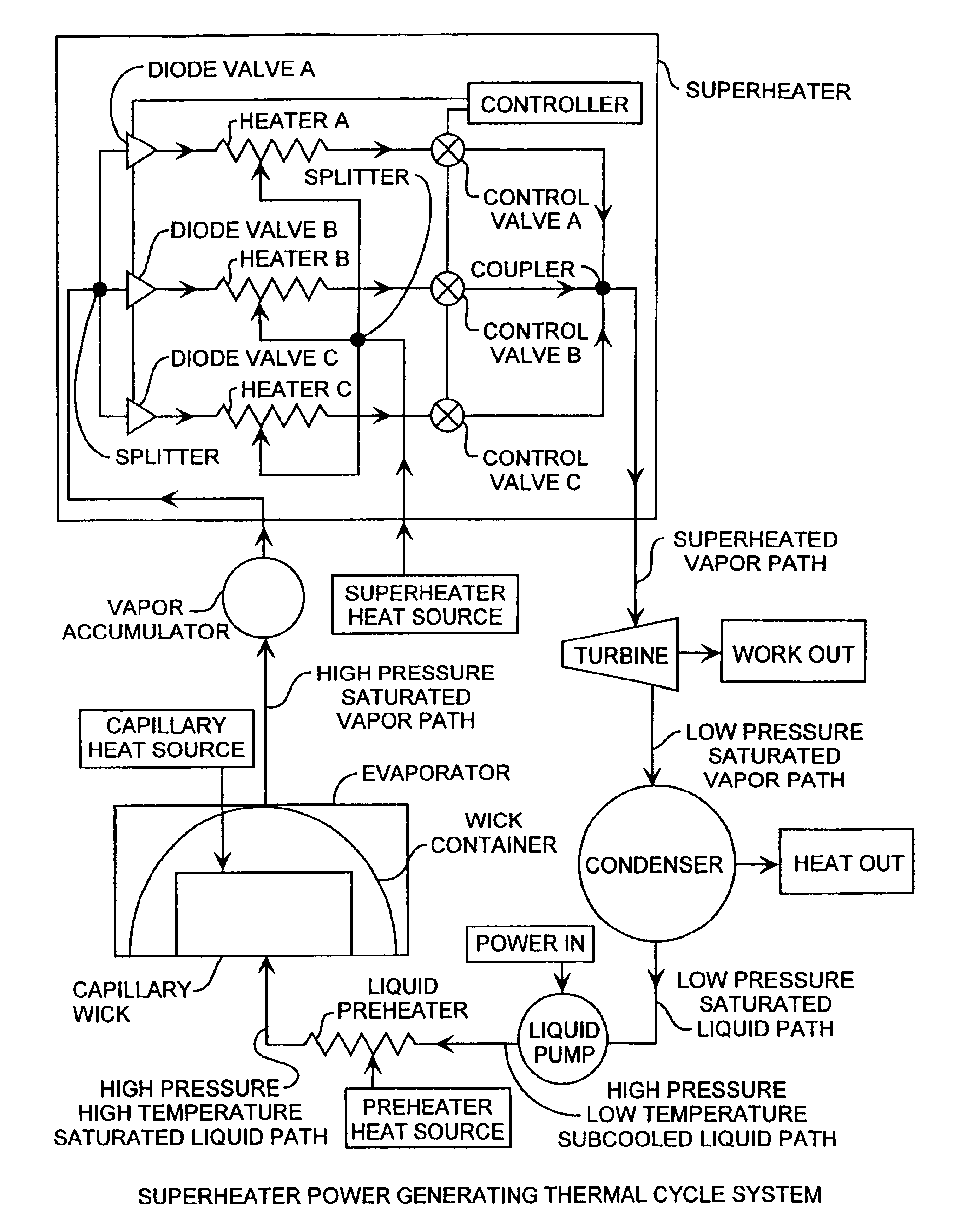
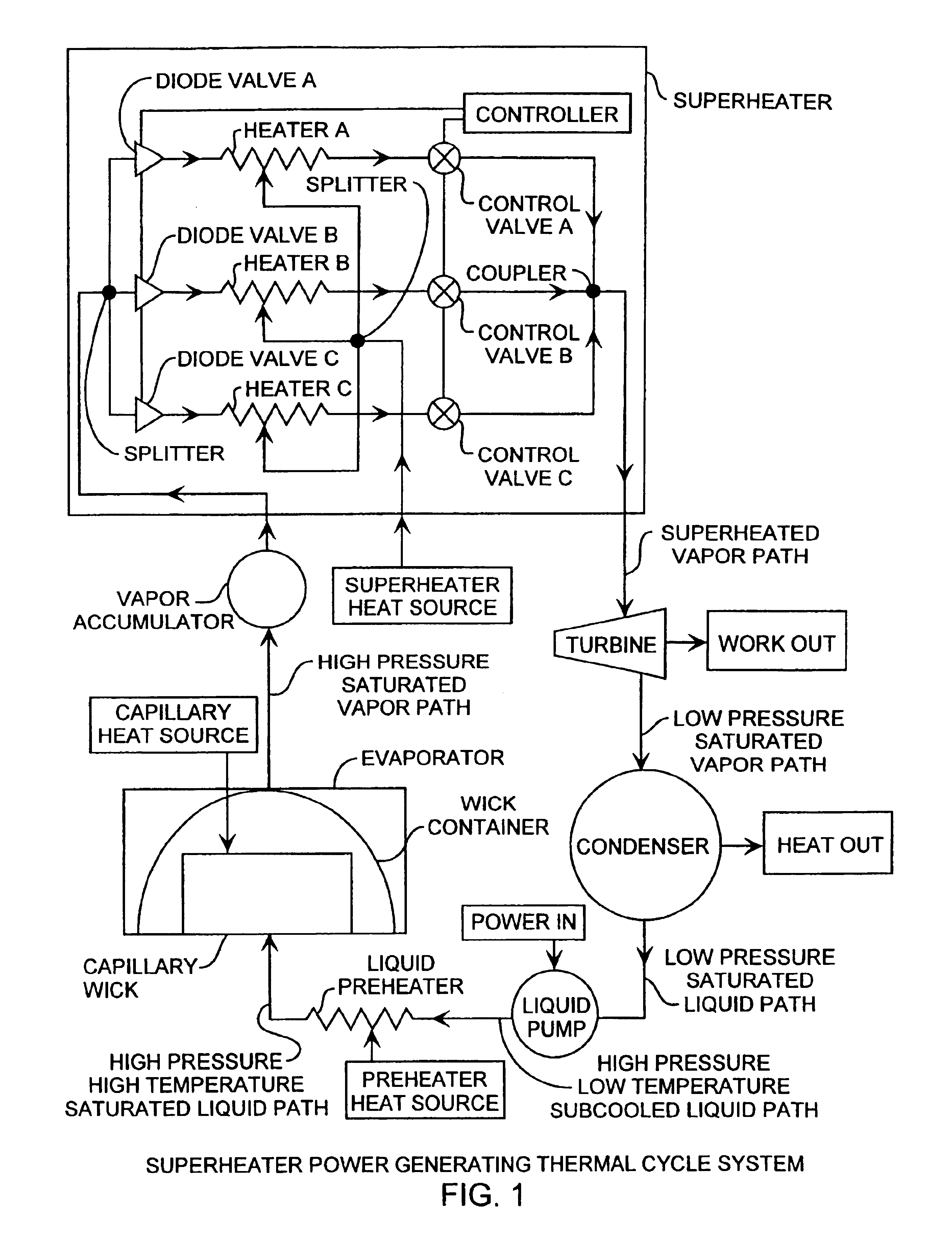
[0032]An embodiment of the invention is described with reference to the figures using reference designations as shown in the Figures. Referring to FIG. 1, a two-phase thermodynamic power system includes a capillary device, a superheater, an inline turbine, a condenser, a liquid pump and a liquid preheater for generating output power. The capillary device, such as a loop heat pipe or a capillary pumped loop, is coupled to an accumulator that is coupled to the superheater. The capillary device includes a capillary wick and a container, combined to make an evaporator. The capillary device is driven by a capillary heat source. The capillary device provides high-pressure saturated vapor through a high-pressure vapor path to a preferred vapor accumulator that is in turn connected to the superheater. The superheater includes a plurality of unidirectional diode valves, such as valves A, B, and C, that are respectively connected to a plurality of heating chambers, such as chambers A, B, and ...


PUM


Abstract

A two-phase thermodynamic power system includes a capillary device, vapor accumulator, superheater, an inline turbine, a condenser, a liquid pump and a liquid preheater for generating output power as a generator. The capillary device, such as a loop heat pipe or a capillary pumped loop, is coupled to a vapor accumulator, superheater, the inline turbine for generating output power for power generation, liquid pump and liquid preheater. The capillary device receives input heat that is used to change phase of liquid received from the liquid preheater, liquid pump and condenser into vapor for extra heating in the superheater used to then drive the turbine. The power system is well suited for space applications using a radioisotope, active nuclear or solar heat source. The system can use waste heat from various dynamic or static power systems as a heat source and waste heat from spacecraft components such as electronics as a heat source. These heat sources can be used separately or in any combination. The power system can be combined with thermal energy storage devices when operated with heat sources that are not steady state. Heat sources are useful for driving the capillary wick, superheater and liquid preheater for increased power efficiency and long lifetime operation. The power system is well suited for space receiving heat from a heat source to produce useful mechanical energy. A superheater in combination with a liquid pump and preheater are implemented for use with the evaporator for improved thermal efficiency while operating at maximum cycle temperatures well below other available power conversion cycles.

Description

REFERENCE TO RELATED APPLICATION[0001]The present application is related to applicant's application entitled Capillary Two-Phase Thermodynamic Power Conversion Cycle System Ser. No. 10 / 431,826, filed May 8, 2003, now U.S. Pat. No. 6,857,269, issued Feb. 22, 2003, by the same inventor, here incorporated by reference as there fully set forth.STATEMENT OF GOVERNMENT INTEREST[0002]The invention was made with Government support under contract No. F04701-00-C-0009 by the Department of the Air Force. The Government has certain rights in the invention.FIELD OF THE INVENTION[0003]The invention relates to the field of thermodynamic power systems. More particularly, the present invention relates to two-phase thermal cycle systems, capillary devices, power generators, thermal condensers and liquid pumps.BACKGROUND OF THE INVENTION[0004]Thermodynamic power cycle systems have typically been used to generate useful work, such as in power generation systems. Thermodynamic power cycles have typicall...

Claims


Application Information

Patent Timeline
Patent Type & Authority Patents(United States)
IPC IPC(8): F01K3/00F01K3/18F22G1/00
CPCF01K3/185F22G1/00
Inventor BAKER, KARL WILLIAM
Owner THE AEROSPACE CORPORATION
Why Eureka
Try Eureka