

Heat exchanger
- Summary
- Abstract
- Description
- Claims
- Application Information
AI Technical Summary
Benefits of technology
Problems solved by technology
Method used
Image

Examples
first embodiment
(First Embodiment)
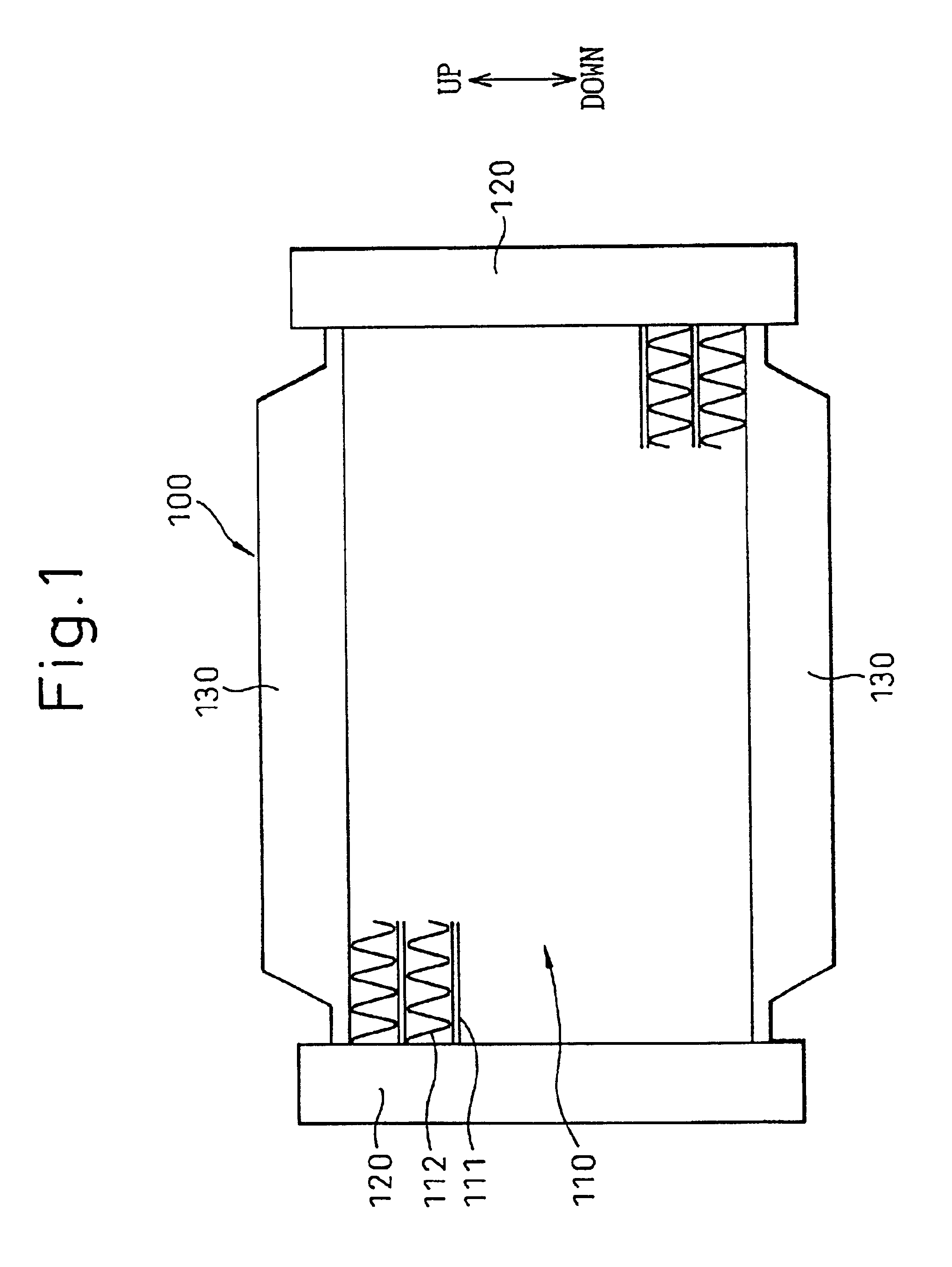
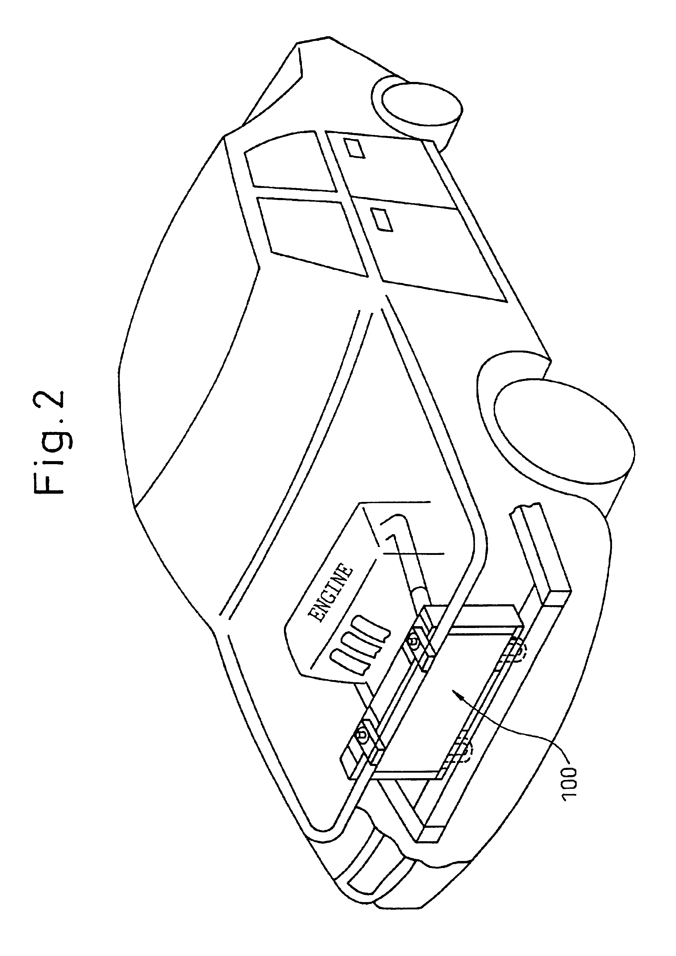
[0027]In this embodiment, a heat exchanger of the present invention is applied to the radiator 100 to cool cooling water by exchanging heat between cooling water (fluid), which cools an internal combustion engine used for driving a vehicle, and air. FIG. 1 is a front view of the radiator 100, that is, FIG. 1 is a view of the radiator 100, wherein the view is taken from the upstream side of the air current. As shown in FIGS. 2 and 3, the radiator 100 is incorporated into a portion close to the front grille, from which cooling air is taken in, which is arranged in the front end portion of a vehicle (engine compartment).
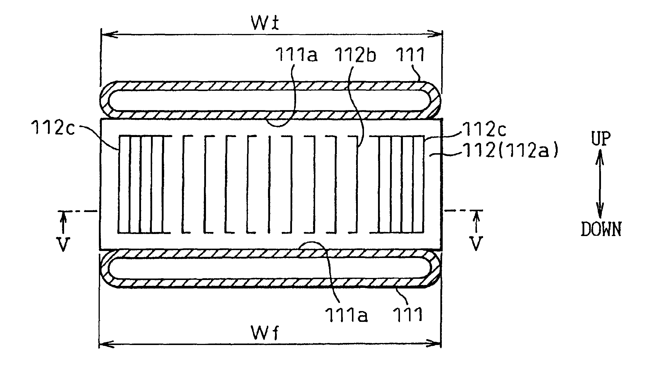
[0028]As shown in FIG. 1, the radiator 100 includes: a core portion 110 composed of a plurality of tubes 111, in which cooling water is circulated, and fins 112 which are arranged between the tubes 111 and formed into a wave shape by means of roller forming; and header tanks 120 which are arranged on both sides of the tubes 111 in the longitudinal dire...
second embodiment
(Second Embodiment)
[0038]In the embodiment described above, the reinforcing portion 112c is provided only on the front grille side which is the upstream side of an air current. However, in this embodiment, as shown in FIGS. 5A and 5B, the reinforcing portion 112c is provided on both end sides (the end portion on the upstream side and the end portion on the downstream side) of the fin 112 in the air flowing direction.
third embodiment
(Third Embodiment)
[0039]In the above embodiment, the reinforcing portion 112c is composed when the fin 112 (the plane portion 112a) is plastically deformed into a wave-shape. As shown in FIGS. 6A and 6B, in this embodiment, the reinforcing portion 112c is composed in such a manner that length L1 of the louver 112b located on the upstream side of the air current of the fin 112 is made to be shorter than length Lo of the louver 112b located at a substantially central portion in the direction of the air current of the fin 112. In this connection, the length (the cutting length) of the louver 112b is defined as the cutting length of the louver 112b perpendicular to the direction of the air current.
[0040]Due to the above structure, the mechanical strength of the fin 112 on the upstream side of the air current becomes higher than that of the substantially central portion of the fin 112. Therefore, the portion of the fin 112, which is directly exposed to water at high pressure, can be prev...
PUM
 Abstract
Description
Claims
Application Information