Dose monitoring method and manufacturing method of semiconductor device

Inactive Publication Date: 2005-07-19
KK TOSHIBA
View PDF6 Cites 7 Cited by
  • Summary
  • Abstract
  • Description
  • Claims
  • Application Information

AI Technical Summary

Problems solved by technology

However, in recent years, demands for miniaturization of the device pattern have become stricter.
As a result, it is difficult to obtain a sufficient dose tolerance and an exposure margin of a focal depth, and this has caused a drop in yield.
If the pattern is made finer, the influence of a focus error on the line width of the pattern cannot be ignored.
Therefore, it is difficult to judge whether the influence is caused by fluctuation of an adequate dose or by fluctuation of a focus position.
Furthermore, also for the duty ratio, in manufacturing a mask, it is difficult to set a pattern increment in design to be extremely fine.
Due to the above-described reaso

Method used


Image

  • Dose monitoring method and manufacturing method of semiconductor device
  • Dose monitoring method and manufacturing method of semiconductor device
  • Dose monitoring method and manufacturing method of semiconductor device

Examples


first embodiment

(First Embodiment)

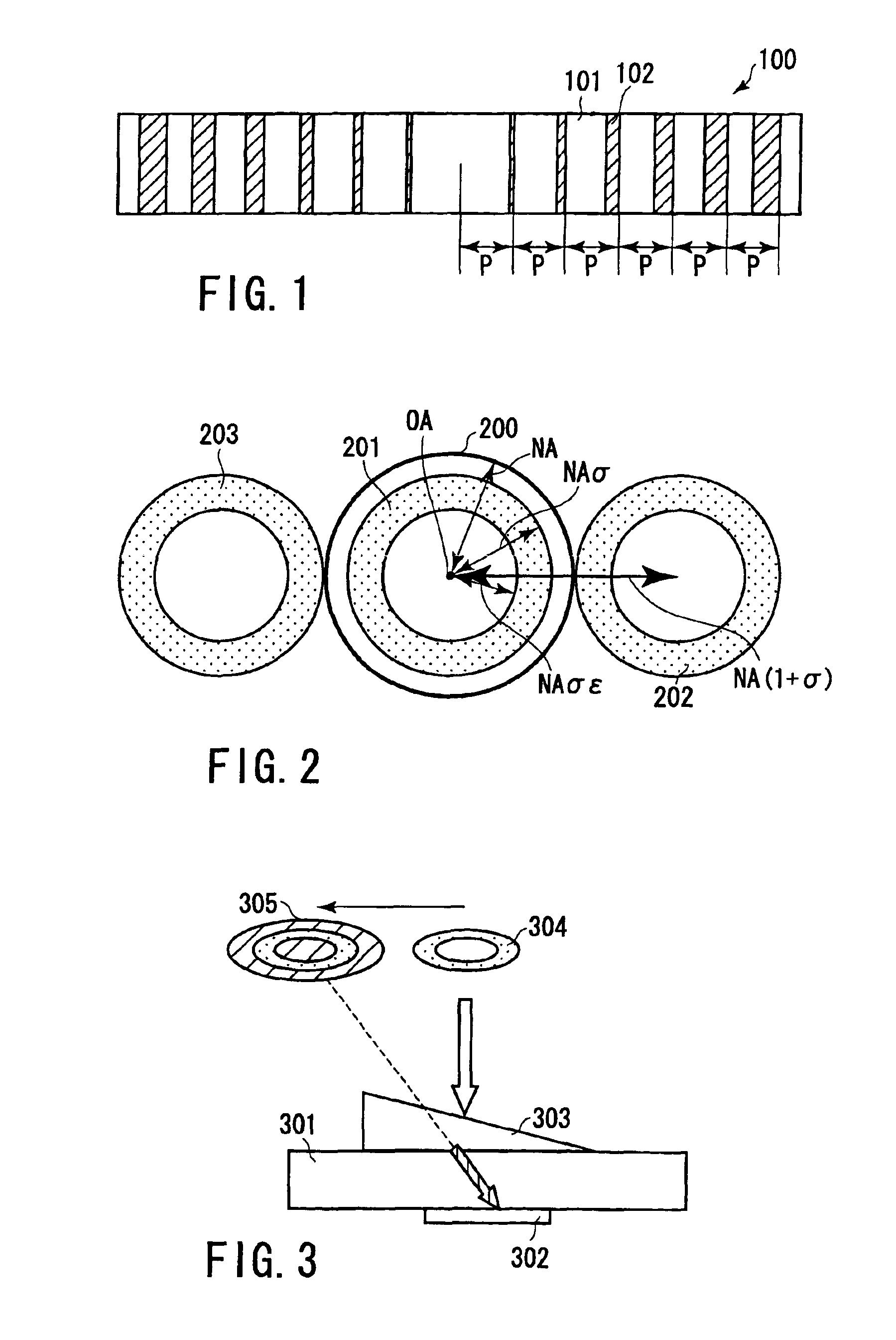
[0072]FIG. 1 is a plan view showing a constitution of a dose monitor pattern according to a first embodiment of the present invention.

[0073]As shown in FIG. 1, in a dose monitor pattern 100, a transmission portion 101 and shield portion 102 are arranged in a block having a width p which is not resolved in an exposure apparatus. A plurality of blocks are continuously arranged in an arrangement direction of the transmission portion 101 and shield portion 102 in the block. Moreover, in the arrangement direction, a duty ratio of the transmission portion 101 to the shield portion 102 in the block monotonously changes. Note that the plurality of blocks may also be intermittently arranged.

[0074]When the dose monitor pattern is irradiated with illumination light, a light intensity distribution of a diffracted light of the dose monitor pattern on a substrate surface monotonously decreases or increases independent of a focal position.

[0075]When a resist film is formed on a s...

second embodiment

(Second Embodiment)

[0102]Furthermore, the present inventors have considered that the illumination is performed from an asymmetric position with respect to the optical axis to form the image, in this case, the position of the formed image of the pattern shifts in a focus state, and this is used to monitor not only the effective dose but also the focus. FIG. 13 concretely shows a method of monitoring the focus.

[0103]A prism 402 is formed on the surface of a transparent substrate 401. On the back surface of the transparent substrate 401, a dose monitor pattern 403, first focus monitor pattern 404, second focus monitor pattern 405, first position shift inspection pattern 406, and second position shift inspection pattern 407 are formed. The dose monitor pattern 403 and first focus monitor pattern 404 are formed under the prism 402.

[0104]This reticle is used to expose a first shot region S1 on a substrate 410. The prism 402 allows the illuminating flux to be eccentric and obliquely incide...

third embodiment

(Third Embodiment)

[0109]In a third embodiment, an effective technique in double pole illumination shown in FIG. 14 will be described in detail. For the double pole illumination, as shown in FIG. 14, two eccentric light sources 501 are disposed symmetrically about a point with respect to the optical axis OA. For concrete illuminating conditions in the present embodiment, a distance σ1 to the center of the eccentric light source 501 from the optical axis OA is 0.65σ, and a size σr of the eccentric light source 501 is 0.2σ. In the same manner as in the first embodiment, the exposure apparatus is the ArF excimer laser exposure apparatus (wavelength λ: 0.193 μm) in which the numerical aperture NA is 0.68, and the coherent factor σ is 0.85.

[0110]The present inventors have found that the arrangement direction of the dose monitor pattern is devised in accordance with the shape of the double pole illumination designed for preferable exposure of a main pattern, and accordingly a period of the...


PUM


Abstract

There is disclosed a dose monitor method comprising illuminating a mask with illumination light, which is disposed in a projection exposure apparatus and in which a dose monitor pattern is formed, passing only a 0th-order diffracted light through a pupil surface of the projection exposure apparatus in diffracted lights of the dose monitor pattern, and transferring a 0th-order diffracted light image of the dose monitor pattern onto a substrate to measure dose, wherein during the illuminating, a center of gravity of the 0th-order diffracted light image passed through the dose monitor pattern on the pupil surface of the projection exposure apparatus is shifted from an optical axis of the projection exposure apparatus.

Description

CROSS-REFERENCE TO RELATED APPLICATIONS[0001]This application is based upon and claims the benefit of priority from the prior Japanese Patent Application No. 2002-194927, filed Jul. 3, 2002, the entire contents of which are incorporated herein by reference.BACKGROUND OF THE INVENTION[0002]1. Field of the Invention[0003]The present invention relates to a dose monitoring method for monitoring dose in a lithography process with improved accuracy, and a manufacturing method of a semiconductor device.[0004]2. Description of the Related Art[0005]Due to the demands for miniaturization of a device pattern of a semiconductor device, an exposure wavelength has been reduced, the NA of a projection lens has been raised, and processing techniques have improved. However, in recent years, demands for miniaturization of the device pattern have become stricter. As a result, it is difficult to obtain a sufficient dose tolerance and an exposure margin of a focal depth, and this has caused a drop in yi...

Claims


Application Information

Patent Timeline
IPC IPC(8): G03F7/20G03F7/207H01L21/027
CPCG03F7/70558
Inventor FUJISAWA, TADAHITOINOUE, SOICHISATO, TAKASHIASANO, MASAFUMI
Owner KK TOSHIBA
Why Eureka
Try Eureka