Method of calibrating a spectroscopic device

Inactive Publication Date: 2005-07-19
TYCO HEALTHCARE GRP LP
View PDF9 Cites 114 Cited by
  • Summary
  • Abstract
  • Description
  • Claims
  • Application Information

AI Technical Summary

Benefits of technology

[0022]Also preferably, the acceptable slope range may be subdivided into a plurality of subranges corresponding to a plurality of levels, comprising a first level and one or more subsequent

Problems solved by technology

For millions of diabetics around the world, the use of lancets or other sharp instruments to draw blood for monitoring their insulin levels is a painful process, and one that often builds up calluses on fingers, making the collection of blood even more difficult.
This invasive procedure may be especially difficult to perform on children and therefore particularly trying on parents.
Furthermore, the test strips required for each blood sample are generally not reusable, and when multiple measurements are taken each day, amount to significant costs from the patient's point of view.
Thus, despite the fact that a large number of diabetics should take several measurements throughout each day (for some individuals, physicians recommend testing glucose levels from 4 to 7 times daily), due to the pain, cost, and inconvenience involved, many diabetics do not monitor their glucose levels frequently enough.
One difficulty with glucose measurement spectral analysis, is the spectral overlap between glucose and other chemicals found in blood, often in much greater quantities than glucose.
Glucose concentrat

Method used


Image

  • Method of calibrating a spectroscopic device
  • Method of calibrating a spectroscopic device
  • Method of calibrating a spectroscopic device

Examples


Embodiment Construction

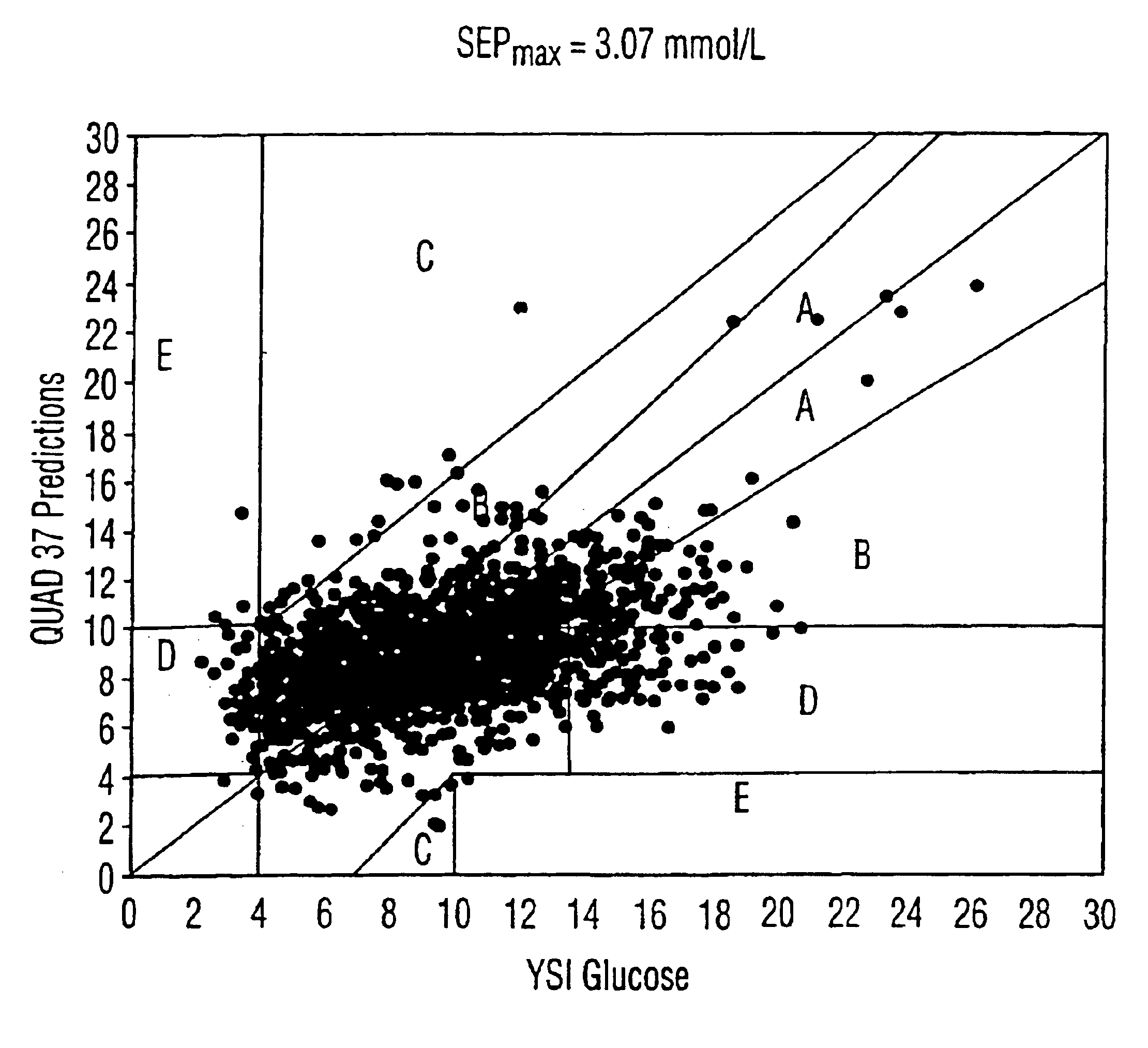
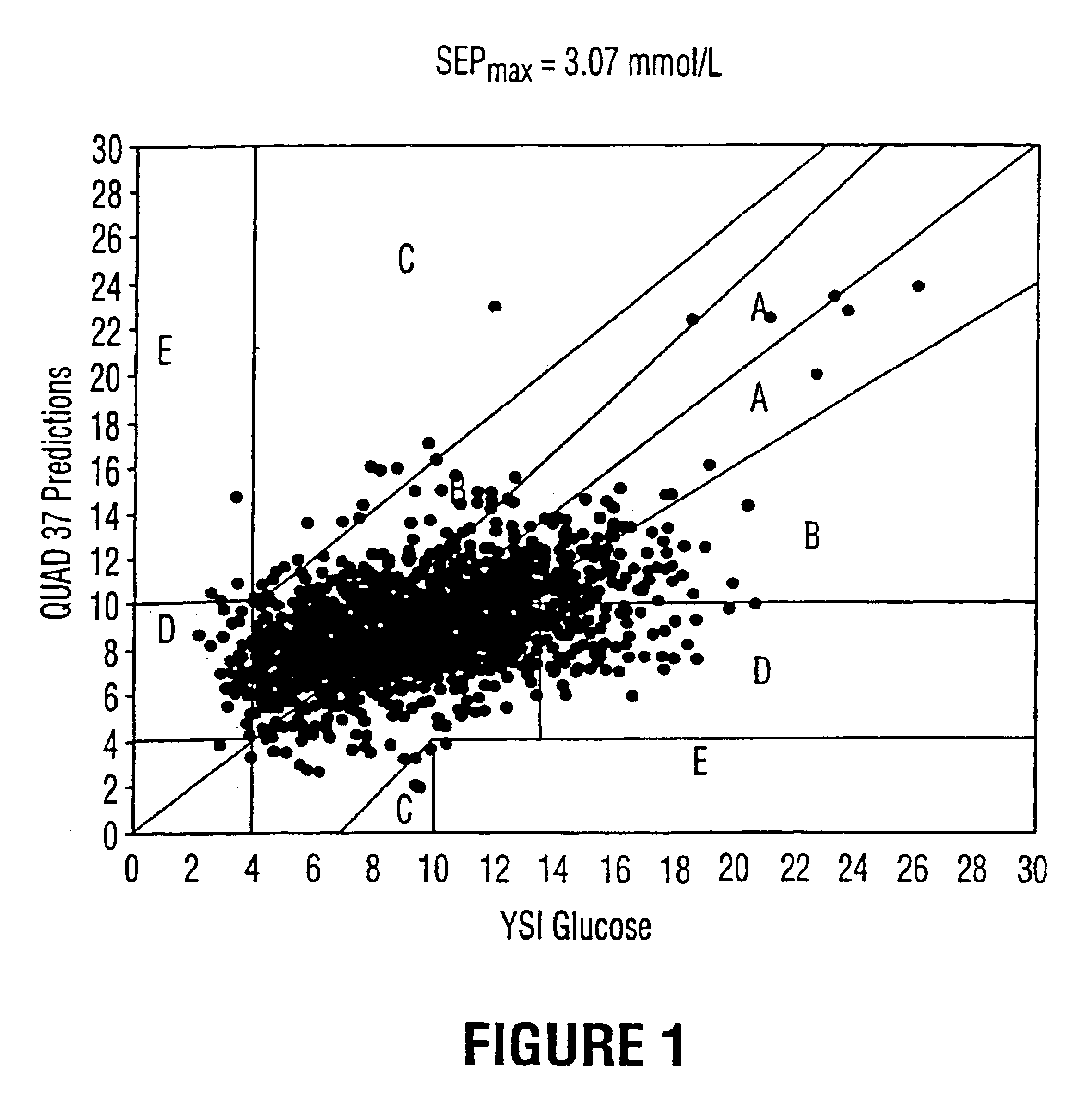
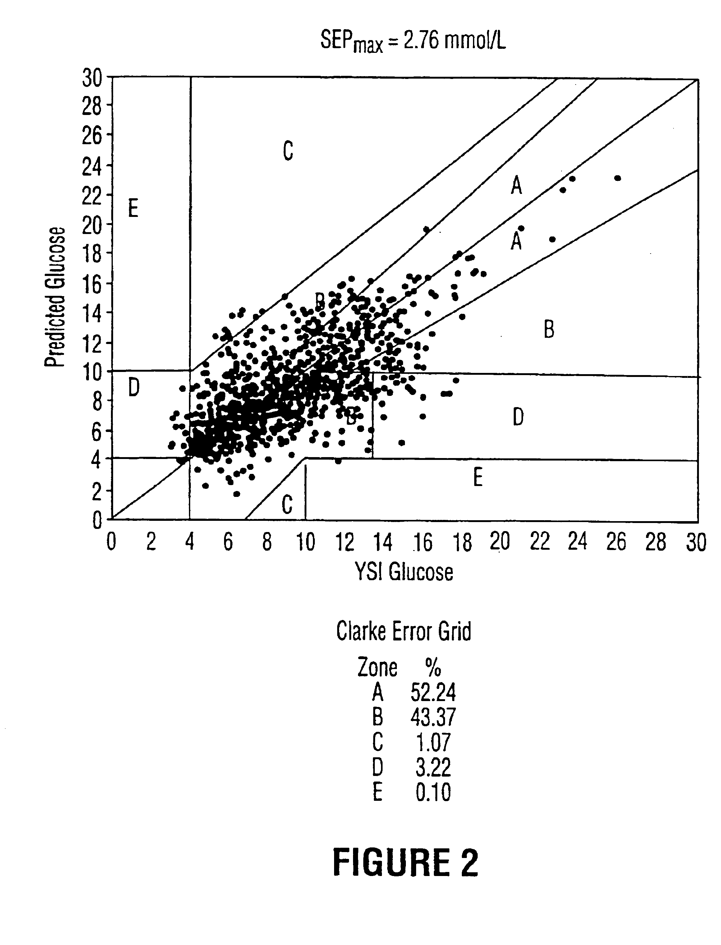
[0036]As mentioned, the present invention relates to a method of calibrating a spectroscopic device for predicting analyte levels in a non-invasive manner. The present invention can be used with a typical NIR spectrophotometer system having a light source which is projected through the item to be examined, a sample interface mechanism, a spectrometer to separate the light into its component wavelengths, a detector, amplification electronics and a computer. By measuring the loss (absorption), between the source and the detector and applying appropriate chemometric (mathematical) techniques, it is possible to non-invasively determine the chemicals being examined since different chemicals absorb different amounts of light at different wavelengths. Such a spectrophotometric device and method are described in detail in U.S. Pat. No. 5,361,758, the contents of which are incorporated herein by virtue of this reference. While the present description relates primarily to glucose measurement,...


PUM


Abstract

The present invention provides a method of calibrating a spectroscopic device for providing a non-invasive measurement of an analyte level in a sample. The method comprises the steps of: (a) providing a plurality of calibration algorithms; (b) taking a set of non-invasive measurements on said sample with said spectroscopic device; (c) calculating a predicted set of analyte levels for each of the calibration algorithms in response to the set of non-invasive measurements, each of the predicted sets of analyte levels being characterized by a variability range, a slope, an R<?img id="CUSTOM-CHARACTER-00001" he="2.46mm" wi="1.78mm" file="US06919566-20050719-P00900.TIF" alt="custom character" img-content="character" img-format="tif" ?>2<?img id="CUSTOM-CHARACTER-00002" he="2.46mm" wi="1.78mm" file="US06919566-20050719-P00900.TIF" alt="custom character" img-content="character" img-format="tif" ?> (a square of the correlation between said set of non-invasive measurements and said predicted set of analyte levels), and a standard error of prediction; and (d) selecting an appropriate calibration algorithm by using a suitability score based on the variability range, the slope, the R2 an the standard error of prediction for each of the predicted sets of analyte levels. A method of generating suitable calibration algorithms in step (a) is also provided.

Description

FIELD OF THE INVENTION[0001]The present invention relates to the fields of spectroscopy, spectrophotometry, and chemometrics. In particular, the present invention relates to a method of calibrating a spectroscopic device for predicting analyte levels in a non-invasive manner. The method of the present invention is particularly suitable for blood glucose prediction based on near-infrared spectrophotometry measurements.BACKGROUND OF THE INVENTION[0002]Biotechnological analysis and examination are often based on the measurement of various chemical analytes in the composition of a biological matrix such as blood, interstitial fluid, or living tissue. Such measurements may be used to evaluate a patient's state of health and to determine what, if any, treatment is necessary. For example, the frequent monitoring of blood glucose levels in diabetic persons with glucose meters is often necessary to allow such persons to manage the diabetes mellitus disease, by taking insulin injections or or...

Claims


Application Information

Patent Timeline
IPC IPC(8): A61B5/00G01N21/27G01N21/31G01N21/25G01N21/35
CPCA61B5/1495G01N21/274G01N21/314G01N21/359A61B5/14532G01N2201/129
Inventor CADELL, THEODORE E.
Owner TYCO HEALTHCARE GRP LP
Why Eureka
Try Eureka