Ring-resister controlled DLL with fine delay line and direct skew sensing detector

a technology of dll and ring resistor, which is applied in the direction of digital storage, generating/distributing signals, instruments, etc., can solve the problems of increasing power consumption, requiring a longer time to achieve phase locking, and power consumption much more at high frequency operation, so as to achieve the effect of minimizing jitter

Inactive Publication Date: 2005-07-19
SK HYNIX INC
View PDF23 Cites 29 Cited by
  • Summary
  • Abstract
  • Description
  • Claims
  • Application Information

AI Technical Summary

Benefits of technology

[0012]It is another object of the present invention to provide a delay locked loop for effectively minimizing a jitter by classifying the unit delay elements into two classes, i.e., coarse unit delay elements and fine unit delay elements.

Problems solved by technology

Accordingly, this continuous toggling of the DLL clock increases power consumption and, especially, this power consumption is much more at high frequency operation.
Accordingly, the increase of the unit delay elements causes a wider area of the architecture in the DLL and it takes a longer time to achieve the phase locking.
Also, the longer time for phase locking inevitably consumes a large amount of current.
Furthermore, the delay locked loop has to accompany a little jitter.
However, in the case where an amount of delay in each unit delay element is not small, the jitter which is caused by the difference between the reference signal ref and the feedback signal may have a large amount.

Method used


Image

  • Ring-resister controlled DLL with fine delay line and direct skew sensing detector
  • Ring-resister controlled DLL with fine delay line and direct skew sensing detector
  • Ring-resister controlled DLL with fine delay line and direct skew sensing detector

Examples


first embodiment

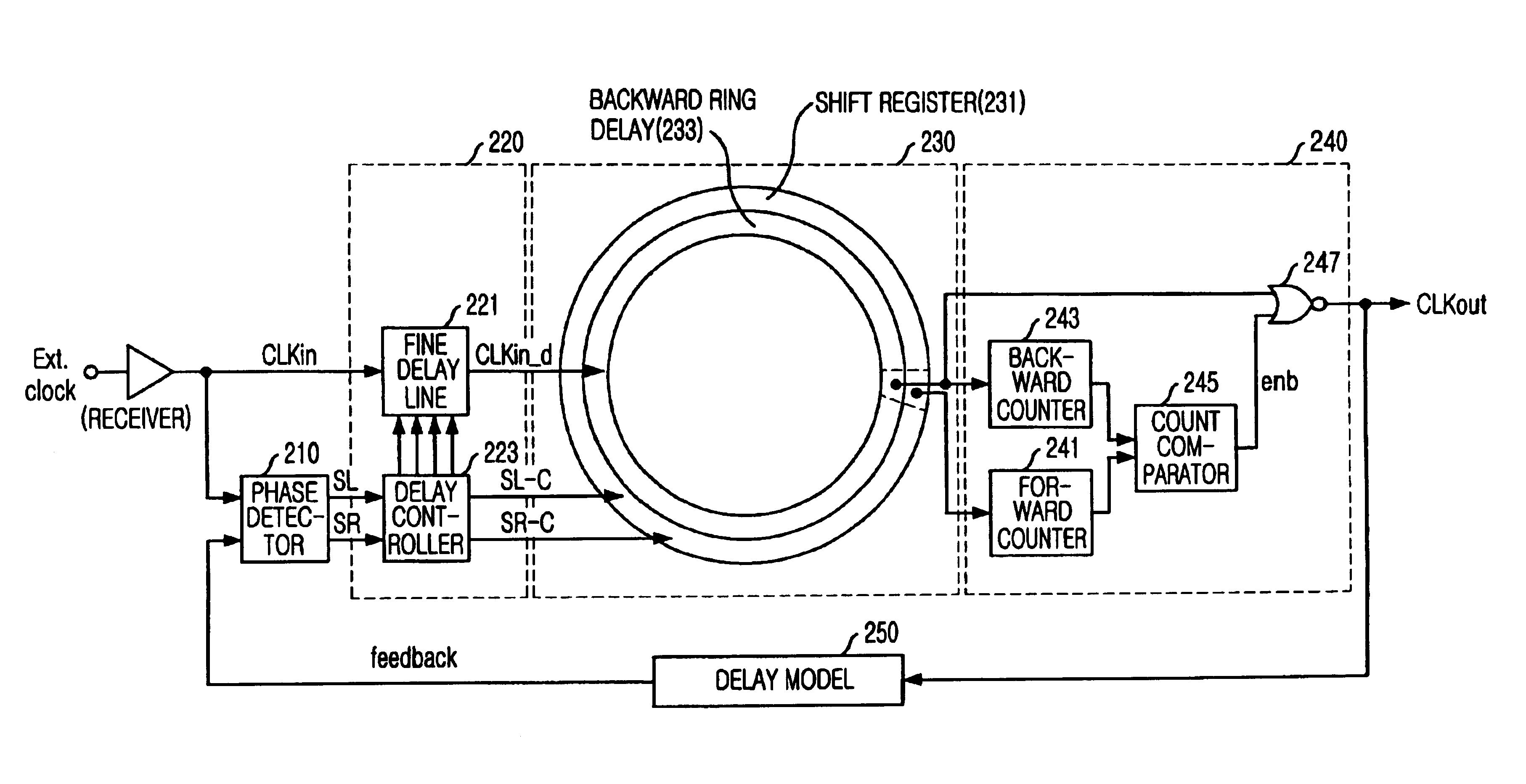
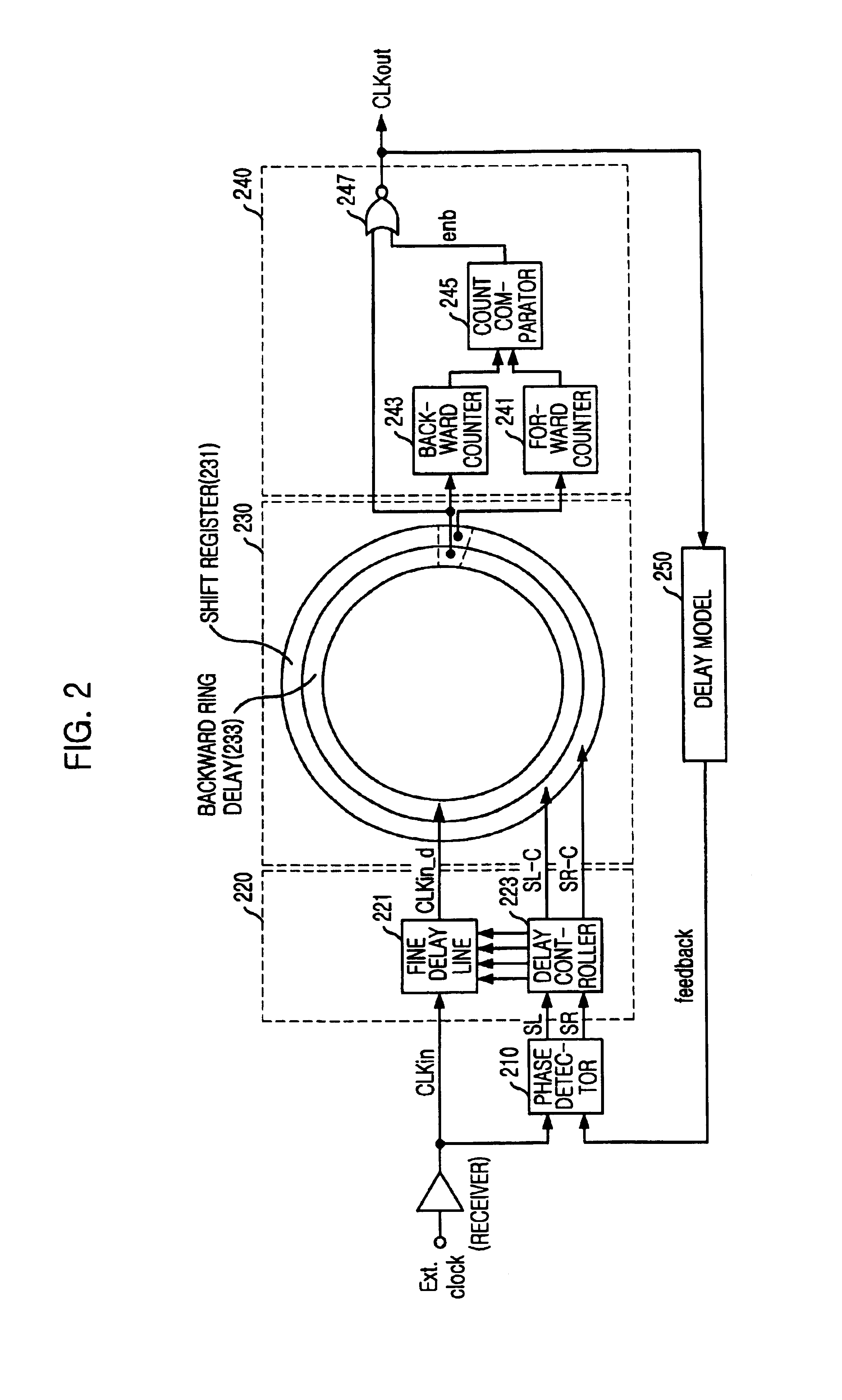
[0041]Referring to FIG. 2, the ring-register controlled DLL according to the present invention includes: a phase detector 210 to detect a phase difference between an internal clock signal CLKin and a feedback signal, which is produced by delaying an output clock signal CLKout through a delay model and feeding back the delayed output clock signal CLKout, and to output a shift left signal SL and a shift right signal SR; a fine delay unit 220 to delicately delay the internal clock signal CLKin in response to the shift left and right signals SL and SR or to by-pas the shift left and right signals SL and SR; a coarse delay unit 230 having a plurality of unit delayers in a ring type to delay an output from the fine delay unit 220 in response to the shift left and right signals SL and SR; an output unit 240 to generate the output clock signal CLKout when a desired delay is achieved; and a delay model 250 to delay the output clock signal CLKout by a delay time (tDM) through a feedback loop....

second embodiment

[0080]FIG. 9 is a plot showing a relationship between a delay locking time and a jitter in accordance with the present invention.

[0081]Referring to FIG. 9, the delay locking time for two frequencies is only 15 cycles. If the fine unit delay time τFD decreases, the total delay locking time increase, however, the delay locking by the coarse delay does not vary. In this simulation, the total jitter is about 50 psec.

third embodiment

[0082]FIG. 10 is a block diagram illustrating a ring-register controlled delay locked loop in accordance with the present invention.

[0083]Configuration of the ring-register controlled delay locked loop in this embodiment is similar to that in the second embodiment except that the external clock signal is inputted to the phase detector 210 instead of the delayed internal clock signal CLKin. In this case, since it is not necessary to consider a delay in the clock receiver, which is the buffer of the delay model 250, the ring-register controlled delay locked loop can be operated in more accurate to variations of the temperature / process / voltage.


PUM


Abstract

The present invention related to a ring-resister controlled DLL with fine delay line and a direct skew sensing detector, which is applicable to circuitry for compensating skew between external and internal clocks. The ring-register controlled delay locked loop according to the present invention comprises: a first delay group including a plurality of unit delay elements which are lineally coupled to each other for delaying an input clock signal; a second delay group including a plurality of unit delay elements which are circularly coupled to each other for delaying an output signal from the first delay group; a first control means for determining an amount of lineal delay in the first delay group; and a second control means for determining an amount of circular delay in the first delay group.

Description

CROSS REFERENCE TO RELATED APPLICATION[0001]This application is a continuation application of U.S. application Ser. No. 10 / 073,358, filed Feb. 13, 2002 now abandoned, the specification and drawings of which are incorporated herein by reference.FIELD OF THE INVENTION[0002]The present invention related to a delay locked loop (DLL) in a semiconductor memory device; and, more particularly, to a ring-resister controlled DLL with fine delay line and a direct skew sensing detector, which is applicable to circuitry for compensating skew between external and internal clocks.BACKGROUND OF THE PRIOR ART[0003]Generally, in system circuits of semiconductor devices, a clock signal has been used as a reference signal for adjusting operation timing or guaranteeing high-speed operation without an error. When a clock signal from an external circuit is used in an internal circuit, a time delay (or clock skew) is generated and then a DLL has been used to compensate such a time delay by providing the sa...

Claims


Application Information

Patent Timeline
Patent Type & Authority Patents(United States)
IPC IPC(8): G11C7/00G11C7/22G11C11/4076G11C11/407H03K5/13H03K5/135H03L7/089H03L7/08H03L7/081G06F1/10G11C8/00H03K5/131
CPCG11C7/22G11C7/222G11C11/4076H03K5/135H03L7/0814H03L7/089H03L7/0818H03K5/133H03L7/0816G11C8/00
Inventor LEE, SEONG-HOONAHN, JUN-HONGCHOI, JOO-SUN
Owner SK HYNIX INC
Why Eureka
Try Eureka