Controller for FET pass device

a controller and control device technology, applied in the direction of electric variable regulation, process and machine control, instruments, etc., can solve the problems of increasing the power dissipation loss of oring diodes, reverse current can occur, etc., to prevent oscillation, high gain regulation, and high impedance

Active Publication Date: 2005-07-19
INTERSIL INC
View PDF3 Cites 16 Cited by
  • Summary
  • Abstract
  • Description
  • Claims
  • Application Information

AI Technical Summary

Benefits of technology

[0007]A controller for regulating a FET to operate as a pass device according to an embodiment of the present invention includes input, output and gate nodes, a controlled low current device, and an oscillating high gain regulation amplifier. The input, output and gate nodes coupled to a current path input, a current path output and the gate of the FET, respectively. The voltage source provides a regulation voltage level relative to the input node. The controlled low current device is coupled to the gate node and has a control input. The regulation amplifier has a first input coupled to the output node, a second input coupled to the voltage source, and an output coupled to the control input of the controlled low current device to regulate the FET. The regulation amplifier oscillates while regulating a voltage difference between the input and output nodes to the regulation voltage level. The controlled low current device presents a high impedance to the gate node to prevent oscillations from disturbing regulation operation.

Problems solved by technology

In addition, reverse current can occur if the current sharing scheme fails and an individual power supply voltage falls significantly below the others.
Although discrete ORing diodes have been used for some time and are relatively inexpensive to implement, there are several drawbacks to their use.
One problem is the associated increasing power dissipation loss in the ORing diodes as power requirements for the system increases.

Method used


Image

  • Controller for FET pass device
  • Controller for FET pass device
  • Controller for FET pass device

Examples


Embodiment Construction

[0017]The following description is presented to enable one of ordinary skill in the art to make and use the present invention as provided within the context of a particular application and its requirements. Various modifications to the preferred embodiment will, however, be apparent to one skilled in the art, and the general principles defined herein may be applied to other embodiments. Therefore, the present invention is not intended to be limited to the particular embodiments shown and described herein, but is to be accorded the widest scope consistent with the principles and novel features herein disclosed.

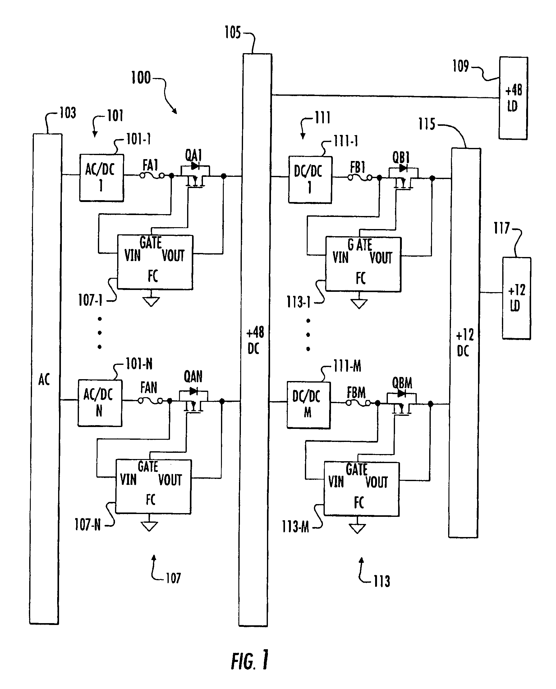
[0018]FIG. 1 is a schematic and block diagram of a redundant power distribution system 100 implemented according to an exemplary embodiment of the present invention. A set of N AC / DC converters 101, individually numbered 101-1 to 101-N (where N is a positive integer), each have an input coupled to an AC power bus 103 and an output coupled to a DC bus 105 to convert AC power to ...


PUM


Abstract

A controller for regulating a FET to operate as a pass device including input, output and gate nodes coupled to a current path input, a current path output and the gate of the FET, respectively, a controlled low current device, and an oscillating high gain regulation amplifier. The voltage source provides a regulation voltage level relative to the input node. The low current device is coupled to the gate node and has a control input. The amplifier has a first input coupled to the output node, a second input coupled to the voltage source, and an output coupled to the control input of the controlled low current device to regulate the FET. The amplifier oscillates while regulating a voltage between the input and output nodes to the regulation voltage level. The controlled low current device presents a high impedance to the gate node to prevent oscillations from disturbing regulation.

Description

BACKGROUND OF THE INVENTION[0001]1. Field of the Invention[0002]The present invention relates to redundant power distribution systems, and more particularly to replacing a power ORing diode with a FET and a controller that operates the FET as a pass device.[0003]2. Description of the Related Art[0004]In a multiple supply fault tolerant redundant power distribution system, the paralleled power supplies are operated to contribute equally to the load current through various power / current sharing schemes. Regardless of the particular current sharing scheme, a common design practice is to include discrete ORing power diodes to protect against reverse current flow should one of the power supplies develop a catastrophic failure resulting in a high current path to ground. In addition, reverse current can occur if the current sharing scheme fails and an individual power supply voltage falls significantly below the others.[0005]Although discrete ORing diodes have been used for some time and a...

Claims


Application Information

Patent Timeline
Patent Type & Authority Patents(United States)
IPC IPC(8): G05F1/10G05F1/575
CPCG05F1/575
Inventor PRESLAR, DONALD R.HAYES, THOMAS J.
Owner INTERSIL INC
Why Eureka
Try Eureka