Broadband monopole/ dipole antenna with parallel inductor-resistor load circuits and matching networks

a dipole antenna and load circuit technology, applied in the direction of antennas, elongated active elements, resonance antennas, etc., can solve the problem of not being the best way to model a load circuit, and achieve the effect of convenient construction

Inactive Publication Date: 2005-07-19
CLEMSON UNIVERSITY
View PDF3 Cites 17 Cited by
  • Summary
  • Abstract
  • Description
  • Claims
  • Application Information

AI Technical Summary

Benefits of technology

[0015]It is an additional object of the present subject matter to utilize circuit configura...

Problems solved by technology

This may not be the best way to model a load circuit, especially if the load circuit comprises p...

Method used


Image

  • Broadband monopole/ dipole antenna with parallel inductor-resistor load circuits and matching networks
  • Broadband monopole/ dipole antenna with parallel inductor-resistor load circuits and matching networks
  • Broadband monopole/ dipole antenna with parallel inductor-resistor load circuits and matching networks

Examples


second embodiment

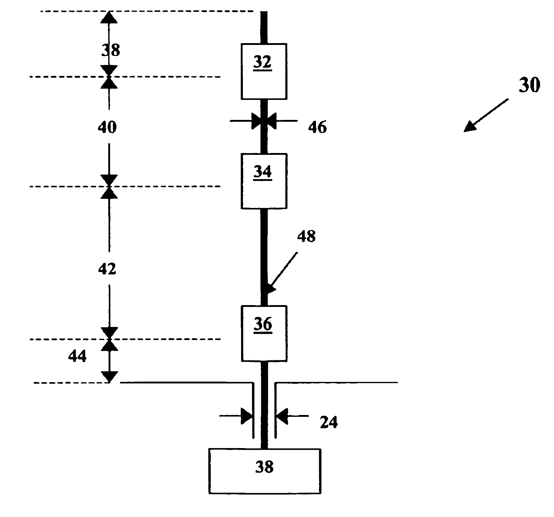
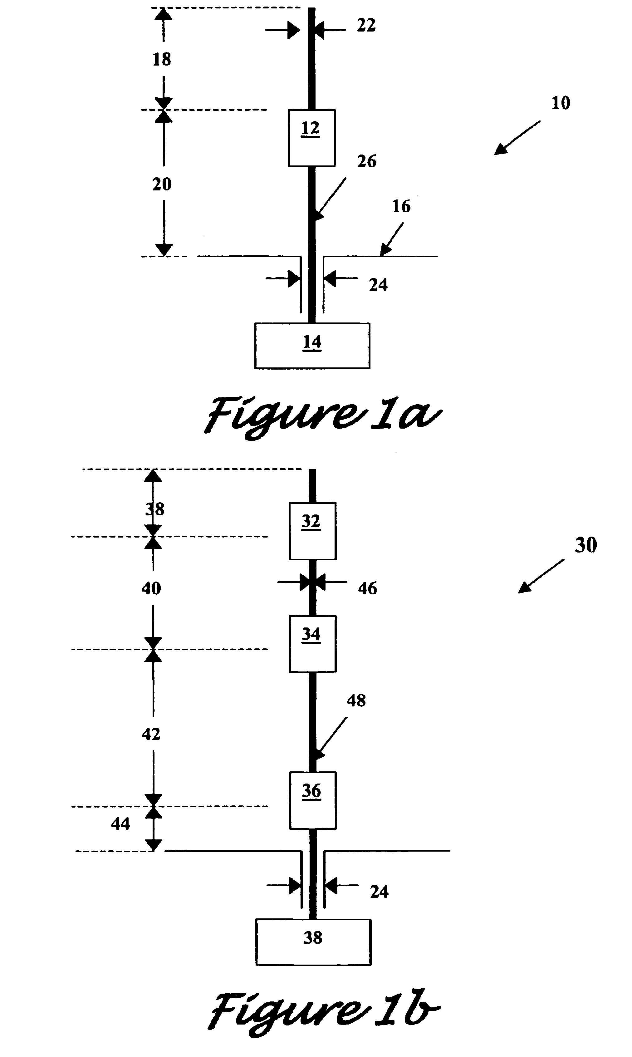
[0075]For such antenna diameter, a corresponding antenna height of 42.5 cm is used. The coils used for constructing the inductors for load circuits 32 and 34 may be constructed by winding 20 AWG wire on standard all-thread dielectrics rods. Such dielectric rods may typically be nylon or teflon of sizes (0.25; 20) or (0.5;13), where a size of (x;y) corresponds to an x-inch diameter and y threads per inch. The rods may then be removed from the coil configuration in order to eliminate dielectric effects caused by the rods. Standard quarter-Watt resistors may be used for the resistor portions of the load circuits. The resistor may then be configured such that it is parallel to the coil, and may be placed either inside or outside the winding to form the parallel LR load. Exemplary specifications for the load circuits as discussed for this second embodiment are presented in the following table, Table 4. Specifications are presented for two exemplary variations of third load 32.

[0076]

TABLE...

embodiment 134

[0082]A present exemplary alternative implementation of an impedance transformer, involving a beaded coaxial cable 132, is much simpler to construct. A schematic illustration of such an embodiment 134 is given in FIG. 5b, wherein the matching network is positioned relative to a ground plane 136 and connected to an antenna 138. Since coaxial cable 132 is used, there is no need to adjust the bifilar windings to achieve the desired characteristic impedance. In order to realize a 1:4 impedance transformation called for in the design process, a 50Ω line is matched to a 200Ω line. The optimal Z0 for the transmission lines in this network is 100Ω, but the exemplary device herein is fabricated from 93Ω line (RG62A / U) since it is readily available. Such line is a flexible cable having a stranded, outer-conductor braid and a solid center conductor. A plastic jacket covers the outer-conductor braid and makes the diameter of the cable 0.6 cm. The jacket and outer conductor braid are preferably ...

first embodiment

[0084]Measured results are available for the exemplary embodiments and parameters provided in the specification. Comparison of computed theoretical antenna performance and measured actual antenna performance is useful in evaluating the effectiveness of actual fabrications. The first exemplary embodiment as discussed in the specification with a single load circuit such as FIG. 1a but with no matching network was analyzed and the results are presented in FIGS. 7a and 7b. FIG. 7a presents measured versus computed voltage standing wave ratio (VSWR) for such first embodiment, and FIG. 7b presents measured versus computed input impedance. Good agreement is observed between the computed and measured data for the embodiment without the matching network.

[0085]Data is also provided for the first embodiment with a matching network such as that illustrated in FIG. 5b. FIG. 8a illustrates the measured versus computed VSWR for such an antenna configuration with single LR load and matching network...


PUM


Abstract

A broadband loaded antenna and matching network with related methods for design optimization are disclosed. The loaded antenna structures may preferably be either monopole or dipole antennas, but the particular methods and techniques presented herein may be applied to additional antenna configurations. The load circuits positioned along an antenna may comprise parallel inductor-resistor configurations or other combinations of passive circuit elements. A matching network for connecting an antenna to a transmission line or other medium preferably includes at least a transmission line transformer and a parallel inductor. Various optimization techniques are presented to optimize the design of such broadband monopole antennas. These techniques include implementation of simple genetic algorithms (GAs) or micro-GAs. Component modeling for selected components may be effected through either lumped element representation or curved wire representation. Measured results are presented to ensure that certain design criteria are met, including low voltage standing wave ratio (VSWR) and high gain over a desired frequency band.

Description

PRIORITY CLAIM[0001]This application claims the benefit of previously filed U. S. Provisional Patent Application with the same inventors and title as present, assigned U.S. Ser. No. 60 / 308,697, filed Jul. 30, 2001, and which is incorporated herein by reference for all purposes.FEDERAL FUNDING[0002]Work was funded in part by the Department of Defense (DoD) through grants DAAH04-1-0247 and DAAG55-98-1-0009.BACKGROUND OF THE INVENTION[0003]The present subject matter generally concerns a broadband antenna with load circuits and matching network, and more particularly concerns a broadband monopole antenna with parallel inductor—resistor load circuits. The subject loaded antenna design may be optimized by various tools including a genetic algorithm and integral equation solver.[0004]Wire antennas have been used in countless communications applications, and often require the ability to provide omnidirectional capabilities over a wide range of frequencies. Many basic antenna configurations ...

Claims


Application Information

Patent Timeline
IPC IPC(8): H01Q9/04H01Q5/00H01Q9/16H01Q9/30H01Q5/321
CPCH01Q9/16H01Q5/321H01Q9/30
Inventor ROGERS, SHAWN D.BUTLER, CHALMERS M.MARTIN, ANTHONY Q.
Owner CLEMSON UNIVERSITY
Why Eureka
Try Eureka