
Hybrid capacitor, circuit, and system

a hybrid capacitor and capacitor technology, applied in the direction of fixed capacitor details, fixed capacitors, printed circuit non-printed electric components association, etc., can solve the problems of dc power and ground line noise, die voltage may collapse, and the available real estate of surface-mounted capacitors becomes a limiting factor

Inactive Publication Date: 2005-07-19
INTEL CORP
View PDF3 Cites 37 Cited by
  • Summary
  • Abstract
  • Description
  • Claims
  • Application Information

AI Technical Summary

Problems solved by technology

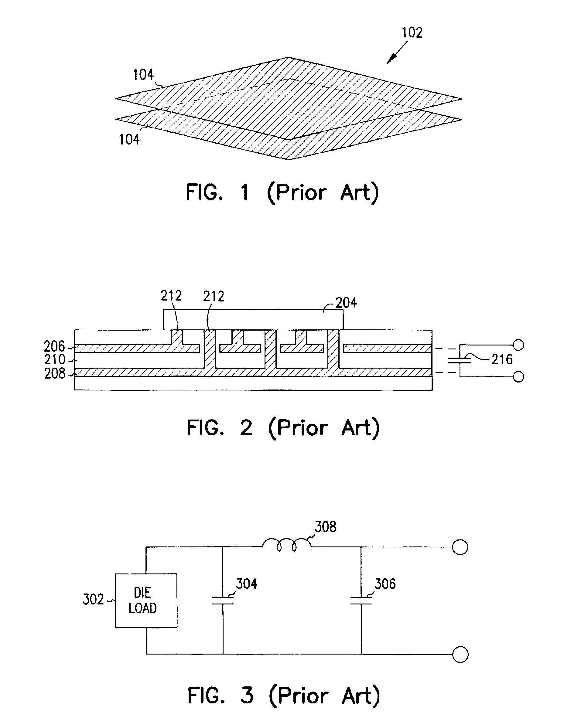
As circuit frequencies delve into the gigahertz (GHz) region, with their associated high frequency transients, noise in the DC power and ground lines increasingly becomes a problem.
If insufficient current is available to the processor, or if the response time of the capacitance is too slow, the die voltage may collapse.
At increasingly reduced device sizes and packing densities, however, available real estate for surface-mounted capacitors becomes a limiting factor.
Increasing the surface area, however, increases the risk of shorts or leakage between the plates, thus reducing yield and increasing reliability concerns.
Besides reliability concerns, the parallel plate capacitor solution may not be sufficient for many higher frequency applications.
This is because the parallel plate capacitance is spread out over a large area, resulting in large lateral parasitics that may prevent the timely flow of charge to “hot spots” on the die (i.e., localized portions of the die that require large amounts of current in short periods of time).
Therefore, the lateral parasitics and relatively high capacitance characteristic of an embedded parallel plate capacitor may unacceptably slow the charge response time to the die hot spots, resulting in a collapse of the die voltage supply.

Method used


Image

  • Hybrid capacitor, circuit, and system
  • Hybrid capacitor, circuit, and system
  • Hybrid capacitor, circuit, and system

Examples


Embodiment Construction

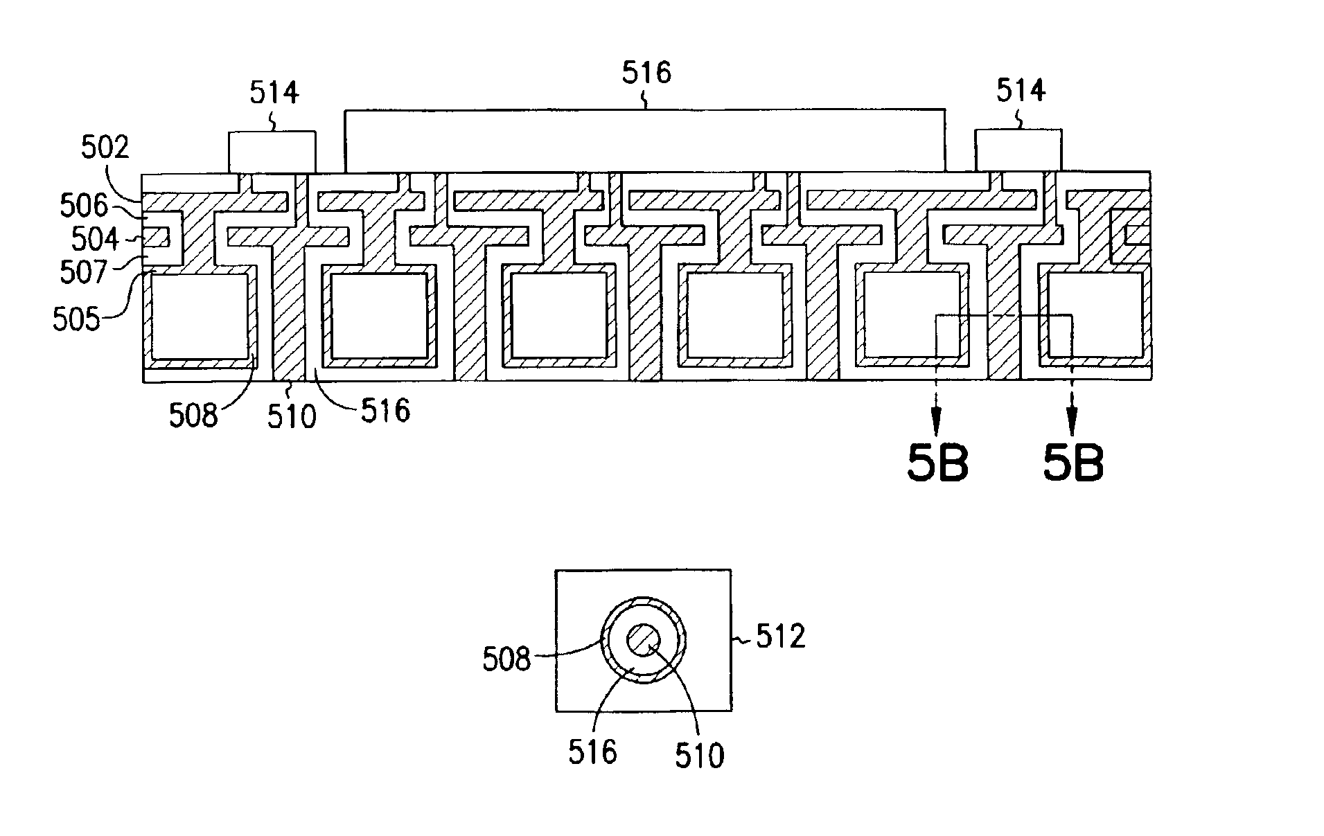
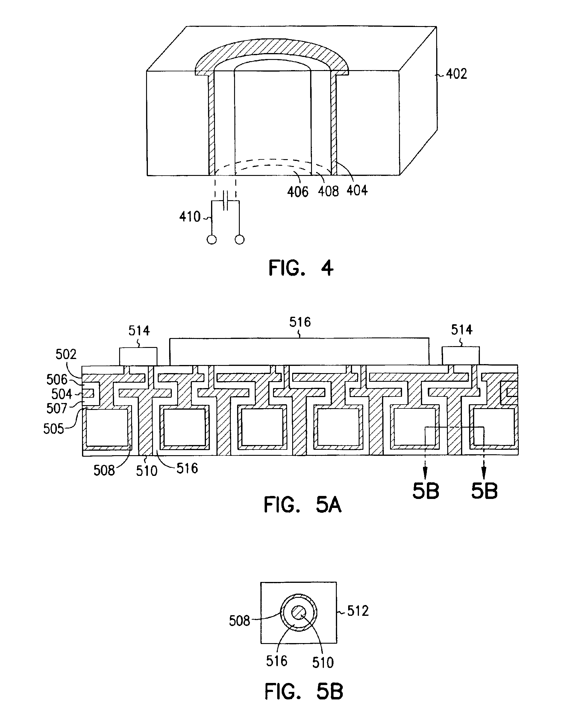
[0029]Various embodiments of the present invention provide a low-inductance, hybrid capacitor structure that effectively suppresses noise, dampens power overshoot and droop, and supplies charge to die hot spots in a timely manner. In one embodiment, the capacitor structure is implemented in and on a device package, and includes an embedded parallel plate capacitor to which an additional high dielectric parallel plate capacitor, discrete capacitors, and self-aligned, coaxial via capacitors are electrically connected. In other embodiments, the embedded parallel plate capacitor is used in conjunction with either the high dielectric parallel plate capacitor, the discrete capacitors, the self-aligned capacitors or some combination of those capacitors, but not all. Either way, the parallel plate capacitor is a first off-chip capacitor that acts as a first source of capacitance, and the high dielectric parallel plate, self-aligned, and / or discrete capacitors are a second set of capacitors ...


PUM

PropertyMeasurementUnit
Thicknessaaaaaaaaaa
Electrical conductoraaaaaaaaaa
Dielectric constantaaaaaaaaaa

Abstract

A hybrid capacitor associated with an integrated circuit package provides multiple levels of excess, off-chip capacitance to die loads. The hybrid capacitor includes a low inductance, parallel plate capacitor embedded within the package, and electrically connected to a second source of off-chip capacitance. The parallel plate capacitor is disposed underneath a die, and includes a top conductive layer, a bottom conductive layer, and a thin dielectric layer that electrically isolates the top and bottom layers. The second source of off-chip capacitance is a set of self-aligned via capacitors, and / or one or more discrete capacitors, and / or an additional parallel plate capacitor. Each of the self-aligned via capacitors is embedded within the package, and has an inner conductor and an outer conductor. The inner conductor is electrically connected to either the top or bottom conductive layer, and the outer conductor is electrically connected to the other conductive layer. The discrete capacitors are electrically connected to contacts from the conductive layers to the surface of the package. During operation, one of the conductive layers of the low inductance parallel plate capacitor provides a ground plane, while the other conductive layer provides a power plane.

Description

[0001]This application is a divisional of application U.S. Ser. No. 09 / 540,705 filed on Mar. 31, 2000 which is now issued as U.S. Pat. No. 6,446,317.TECHNICAL FIELD OF THE INVENTION[0002]The present invention relates generally to apparatus for providing capacitance to a microelectronic circuit, and more particularly to capacitors used in conjunction with a parallel plate capacitor to provide capacitance to a microelectronic circuit, and apparatus utilizing such capacitors.BACKGROUND OF THE INVENTION[0003]Electronic circuits, and particularly computer and instrumentation circuits, have in recent years become increasingly powerful and fast. As circuit frequencies delve into the gigahertz (GHz) region, with their associated high frequency transients, noise in the DC power and ground lines increasingly becomes a problem. This noise can arise due to inductive and capacitive parasitics, for example, as is well known. To reduce such noise, capacitors known as decoupling capacitors are ofte...

Claims


Application Information

Patent Timeline
IPC IPC(8): H01L23/58H01L23/64H05K1/14H05K1/16
CPCH01L23/642H01L2924/15312H01L2924/19105H05K1/141Y10T29/435H01L2924/0002H05K1/162H01L2924/00
Inventor FIGUEROA, DAVID G.LI, YUAN-LIANGDO, HUONG T.
Owner INTEL CORP
Learn More