Therapeutic radiation source with in situ radiation detecting system

a radiation detection and radiation source technology, applied in the field of miniaturized, low-power radiation sources, can solve the problems of imposing considerable hazards to both the handling personnel and the environment, and affecting the safety of patients

Inactive Publication Date: 2005-07-19
CARL ZEISS STIFTUNG DOING BUSINESS CARL ZEISS
View PDF13 Cites 38 Cited by
  • Summary
  • Abstract
  • Description
  • Claims
  • Application Information

AI Technical Summary

Benefits of technology

[0015]The present invention relates to a therapeutic radiation source, for example a miniaturized x-ray source, that includes an in-situ radiation detecting system for monitoring in real time the amount of therapeutic radiation generated by the source. The radiation detecting system generates a signal representative of the generated ...

Problems solved by technology

This treatment suffers from the disadvantage that tissue disposed between the radiation source and the target is exposed to radiation.
Non-cancerous tissues and organs are thus also damaged by the penetrating x-ray radiation.
Handling and disposal of such radioisotopes, however, may impose considerable hazards to both the handling personnel and the environment.
Also, introduction of the radioisotopes requires invasive procedures which have potential side-effects, such as the possibility of infection.
Moreover, there is no ability to provide selective control of time dosage or radiation intensity.
Even though the above-discussed miniature radiation sources can generate x-rays local to the target tissue, it is difficult to provide a uniform, or other desired, dose of radiation to an irregularly shaped target tissue, usi...

Method used


Image

  • Therapeutic radiation source with in situ radiation detecting system
  • Therapeutic radiation source with in situ radiation detecting system
  • Therapeutic radiation source with in situ radiation detecting system

Examples


Embodiment Construction

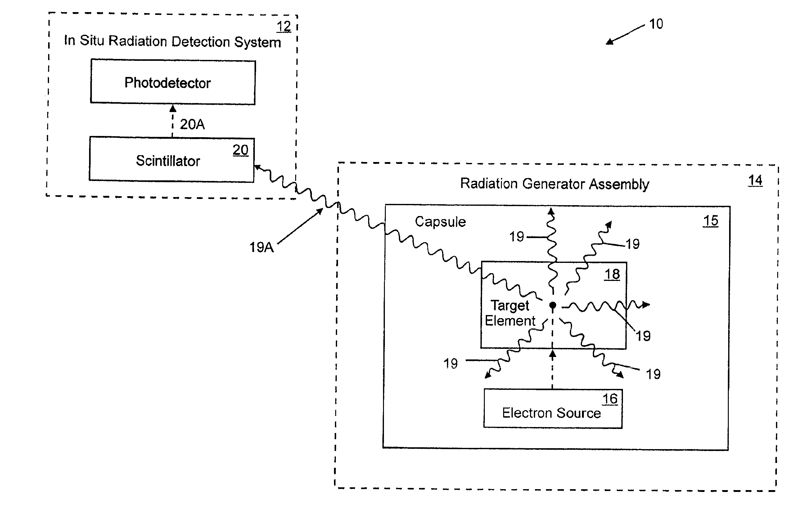
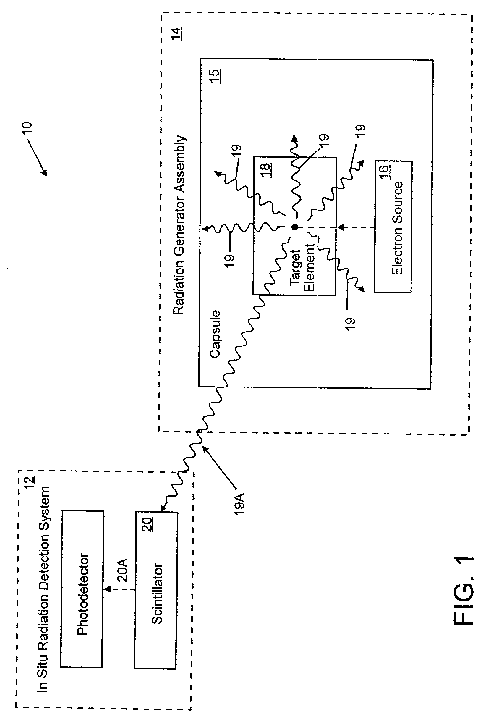
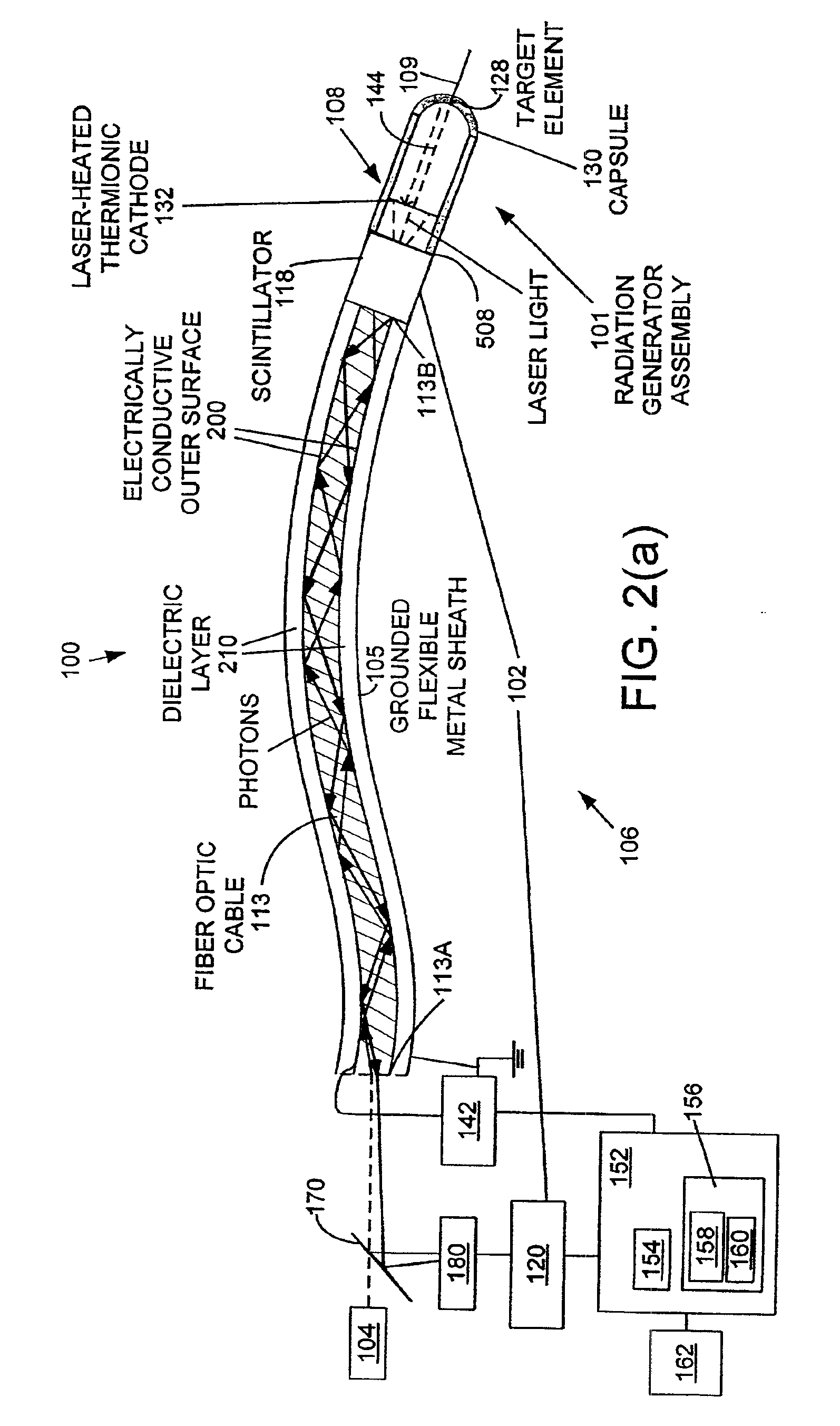
[0028]FIG. 1 is a schematic block diagram of a therapeutic radiation source 10, constructed in accordance with the present invention and including an in situ radiation detection system 12. The therapeutic radiation source 10 includes a radiation generator assembly 14 having an electron source 16, and a target element 18 adapted to emit therapeutic radiation 19 in response to incident accelerated electrons from the electron source 16. The electron source 16 and the target element 18 are enclosed within an evacuated capsule 15. The in situ radiation detecting system 12 monitors in real time the amount of therapeutic radiation 19 emitted by the target element 18. In a preferred embodiment, the therapeutic radiation 19 are x-rays, although the scope of this invention is not limited to x-rays. The in situ radiation detecting system 12 includes a scintillator 20 disposed along a path of a portion (19A) of the emitted therapeutic radiation. The scintillator 20 emits scintillator light 20A ...


PUM


Abstract

A therapeutic radiation source includes an in situ radiation detecting system for monitoring in real time an amount of the therapeutic radiation that has been generated. An electron source generates electrons in response to light that is transmitted through a fiber optic cable and impinges upon the electron source. The electrons are accelerated toward the target and strike the target, causing the target to emit therapeutic radiation, such as x-rays. A scintillator is disposed along a path of a portion of the emitted therapeutic radiation, and generates scintillator light corresponding to the intensity of the therapeutic radiation that is incident upon the scintillator. A photodetector in optical communication with the scintillator produces a signal indicative of the intensity of the therapeutic radiation incident upon the scintillator.

Description

CROSS-REFERENCE TO RELATED APPLICATIONS[0001]Not ApplicableSTATEMENT REGARDING FEDERALLY SPONSORED RESEARCH[0002]Not ApplicableREFERENCE TO MICROFICHE APPENDIX[0003]Not ApplicableFIELD OF THE INVENTION[0004]The present invention relates to a miniaturized, low power radiation source for use in generating therapeutic radiation.BACKGROUND[0005]In the field of medicine, radiation may be used for diagnostic, therapeutic and palliative purposes. Therapeutic use of radiation such as x-rays and γ-rays typically involves-using these rays to eradicate malignant cells. Conventional radiation treatment systems used for medical treatment, such as the linear accelerators that produce high-energy x-rays, utilize a remote radiation source external to the targeted tissue. A beam of radiation is directed at the target area, for example a malignant tumor inside the body of a patient. The x-rays penetrate the patient's body tissue and deliver x-ray radiation to the cancer cells, usually seated deep ins...

Claims


Application Information

Patent Timeline
IPC IPC(8): G21G4/00A61N5/10G01T1/20G21K1/06H01J35/06H05G1/36
CPCA61N5/1048G01T1/2018H01J35/065H05G1/36
Inventor DINSMORE, MARK
Owner CARL ZEISS STIFTUNG DOING BUSINESS CARL ZEISS
Why Eureka
Try Eureka