
RF generating system with fast loop control

a generating system and loop control technology, applied in the field of rf power generation, can solve the problems of low efficiency and inadequate frequency response, and achieve the effects of low cost, low cost, and low cos

Inactive Publication Date: 2005-07-19
LAM RES CORP
View PDF34 Cites 103 Cited by
  • Summary
  • Abstract
  • Description
  • Claims
  • Application Information

AI Technical Summary

Benefits of technology

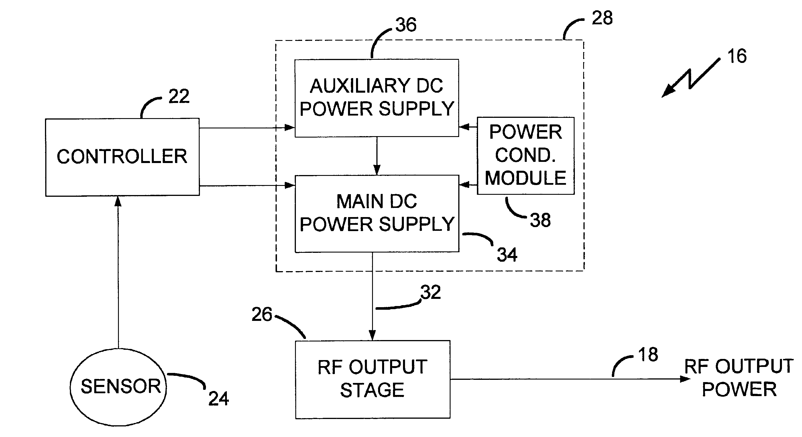
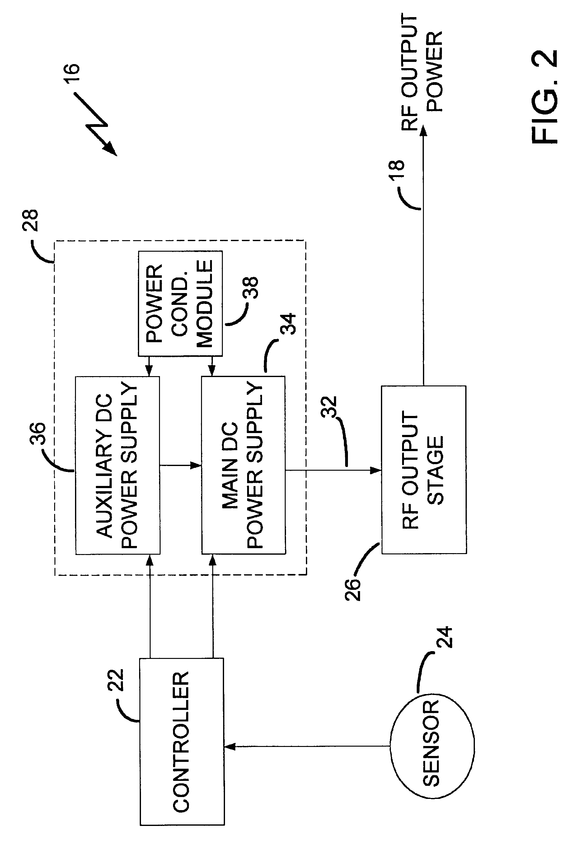
[0013]The second power supply may be an auxiliary power source operating as a function of a feedback signal to boost (raise) and / or buck (lower) the DC power supplied by the first power supply. The feedback signal may provide indication of potentially unstable tendencies within the plasma processing system. The first power supply may provide high efficiency operation of the RF generating system. The second power supply may provide suppression of residual switching ripple, harmonics and other noise. In addition, the second power supply may provide the capability for fast, relatively small modulation of the DC power supplied to the RF output stage in response to the feedback signal.
[0014]During operation in the plasma processing system, the RF generating system may suppress instabilities, such as, for example, instabilities in the plasma. The instabilities may be suppressed through operation of a first control loop to modulate the DC power supplied by the first power supply as a function of the RF setpoint. In addition, a second control loop may modulate the DC power supplied by the second power supply as a function of the feedback signal.
[0015]The first control loop may operate with a relatively low frequency response to adjust the RF output power as a function of the RF setpoint. The second control loop may operate with a relatively high frequency response, up to the frequency of the RF output power, to modulate generation of the RF output power in opposition to any unstable tendencies. As such, the RF output power may be modulated in a region around the operating point to maintain the stability of plasma. Accordingly, the first and second power supplies may cooperatively operate to provide wide bandwidth, relatively small amplitude modulation capability for the RF output power, while maintaining overall operating efficiency.
[0016]With the fast feedback configuration of the second control loop, the modulation capability of the RF output stage may create a local metastable region at the operating point independent of the slope of the load impedance characteristic at that point. In other words, the fast feedback configuration may provide a mechanism for controlling the effective impedance of the plasma to suppress instabilities within the plasma processing system. As a result, fluctuations in the impedance of the plasma may be controlled by high frequency adjustments in the RF power to assist in maintaining the plasma in a stable operating region around the desired operating point.

Problems solved by technology

The first power supply may be a relatively high efficiency design with inadequate frequency response to dynamically stabilize the load on the RF generating system.

Method used


Image

  • RF generating system with fast loop control
  • RF generating system with fast loop control
  • RF generating system with fast loop control

Examples


Embodiment Construction

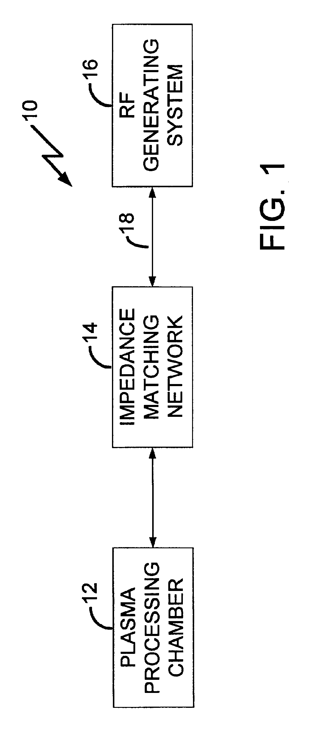
[0023]The presently preferred embodiments provide a method and system for maintaining stability within a plasma processing system. The plasma processing system includes an RF generating system supplying RF power for a plasma discharge. The plasma discharge may be formed and / or biased by the RF power generated by the RF generating system. The RF generating system may vary the amplitude of the RF power to maintain the stability of the plasma processing system. During operation, the RF generating system may modulate the level of the RF power at frequencies up to the frequency of the RF power. Adjustment of the RF power may occur fast enough to minimize unstable tendencies that may create undesirable variations in the impedance of the plasma discharge. As such, the plasma processing system may be maintained in a stable operating range.

[0024]FIG. 1 illustrates a plasma processing system 10 that includes a plasma-processing chamber 12, an impedance matching network 14 and an RF generating...


PUM


Abstract

An RF generating system operates with high efficiency to supply RF output power to a plasma load. The RF generating system is capable of modulating the RF output power at frequencies up to the frequency of the RF output power while maintaining high efficiency operation. Broadband frequency modulation of the RF output power suppresses instabilities thereby minimizing unstable behavior of the plasma load.

Description

[0001]This application claims the benefit pursuant to 35 U.S.C. §119(e) of Provisional U.S. patent application Ser. No. 60 / 294,885 filed on May 31, 2001.FIELD OF THE INVENTION[0002]The present invention relates to RF power generation to create and maintain a plasma and, more particularly, to an RF generating system with an RF output stage which may be modulated to minimize instabilities.BACKGROUND[0003]Material processing using plasma is a well-known technique. Processing is performed on a workpiece such as glass plates, semiconductor wafers or metal substrates. The processing may involve modification of a surface of the workpiece using the plasma, deposition of a thin film on the surface, and / or etching the film with the plasma. Gas plasma is formed through electrical excitation of a gas to produce electron-ion pairs.[0004]In general, systems for material processing with plasma typically include a plasma chamber containing, or adjacent to, a plasma source powered by a radio frequen...

Claims


Application Information

Patent Timeline
IPC IPC(8): H04B7/00H04B1/00H01J37/32
CPCH01J37/32082H01J37/32174
Inventor BENJAMIN, NEIL
Owner LAM RES CORP
Learn More