
Compensation scheme for reducing delay in a digital impedance matching circuit to improve return loss

ompensation scheme technology, applied in the field of impedance matching circuits, can solve the problems of amplitude difference, worse return loss, and problematic digital implementation of impedance matching networks, and achieve the effects of reducing delay in a digital impedance matching circuit, improving return loss, and improving impedance matching

Active Publication Date: 2005-07-19
TEXAS INSTR INC
View PDF7 Cites 5 Cited by
  • Summary
  • Abstract
  • Description
  • Claims
  • Application Information

AI Technical Summary

Benefits of technology

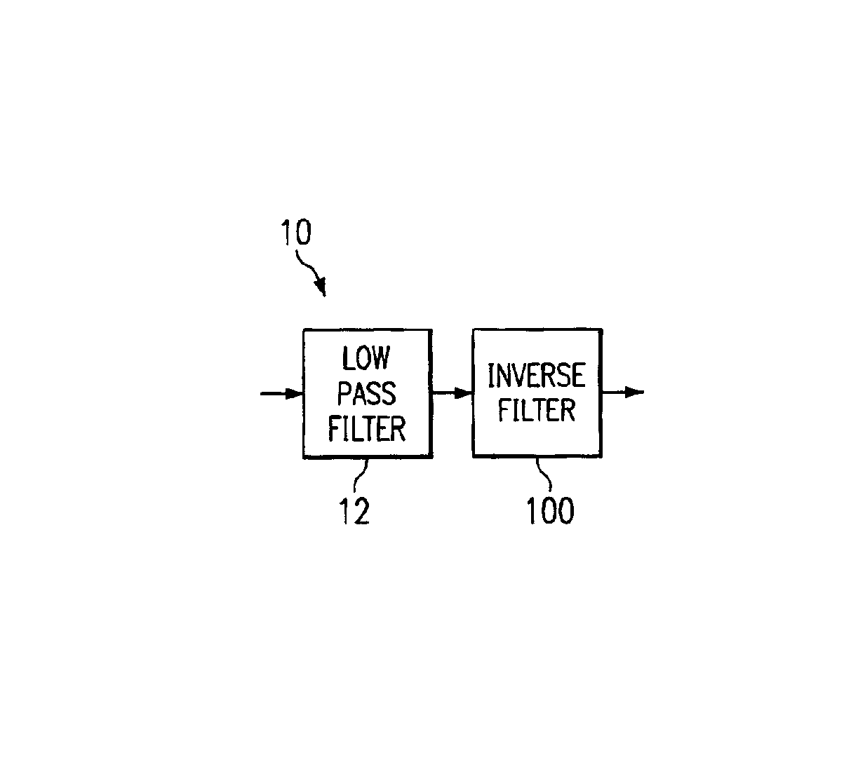
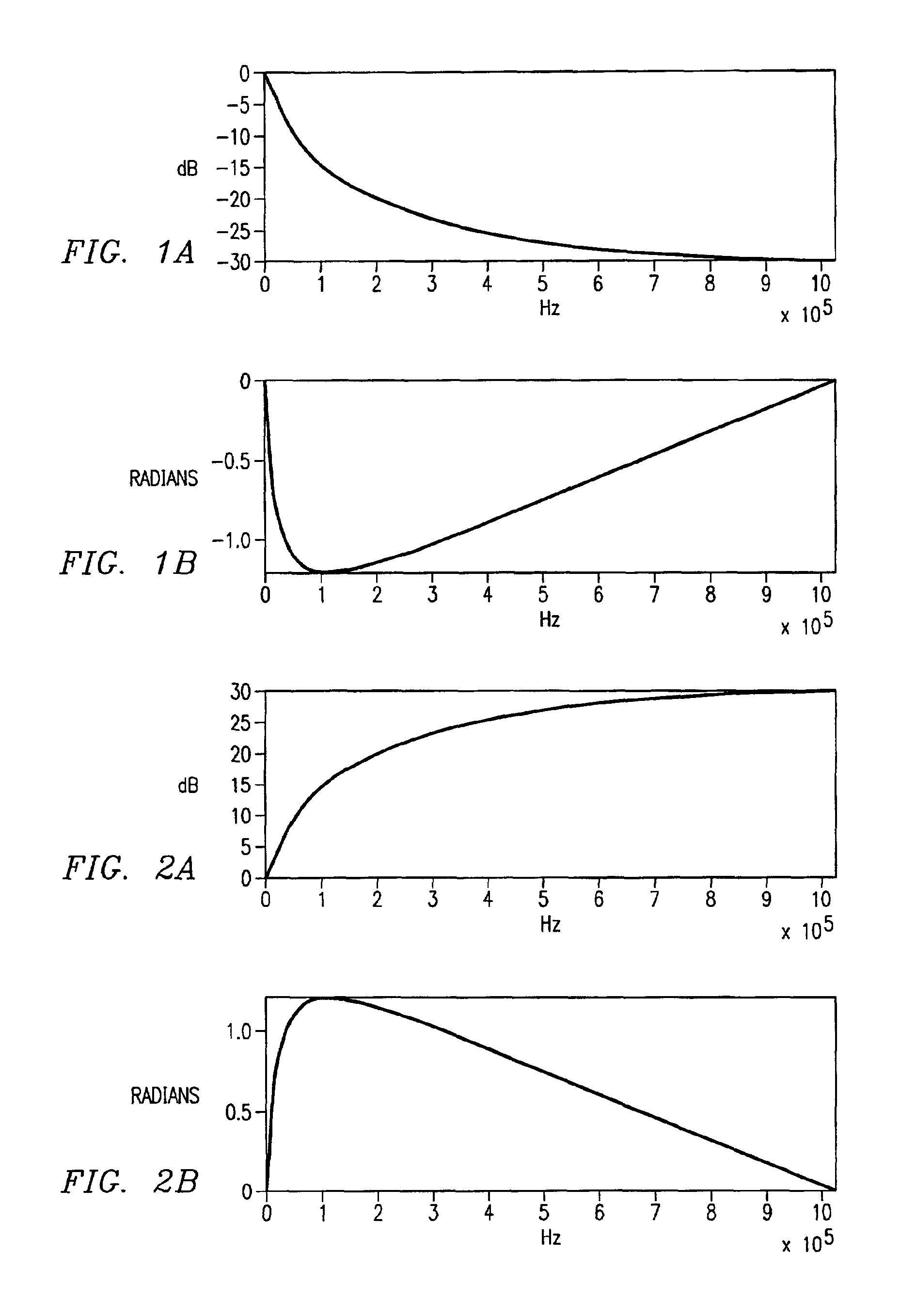
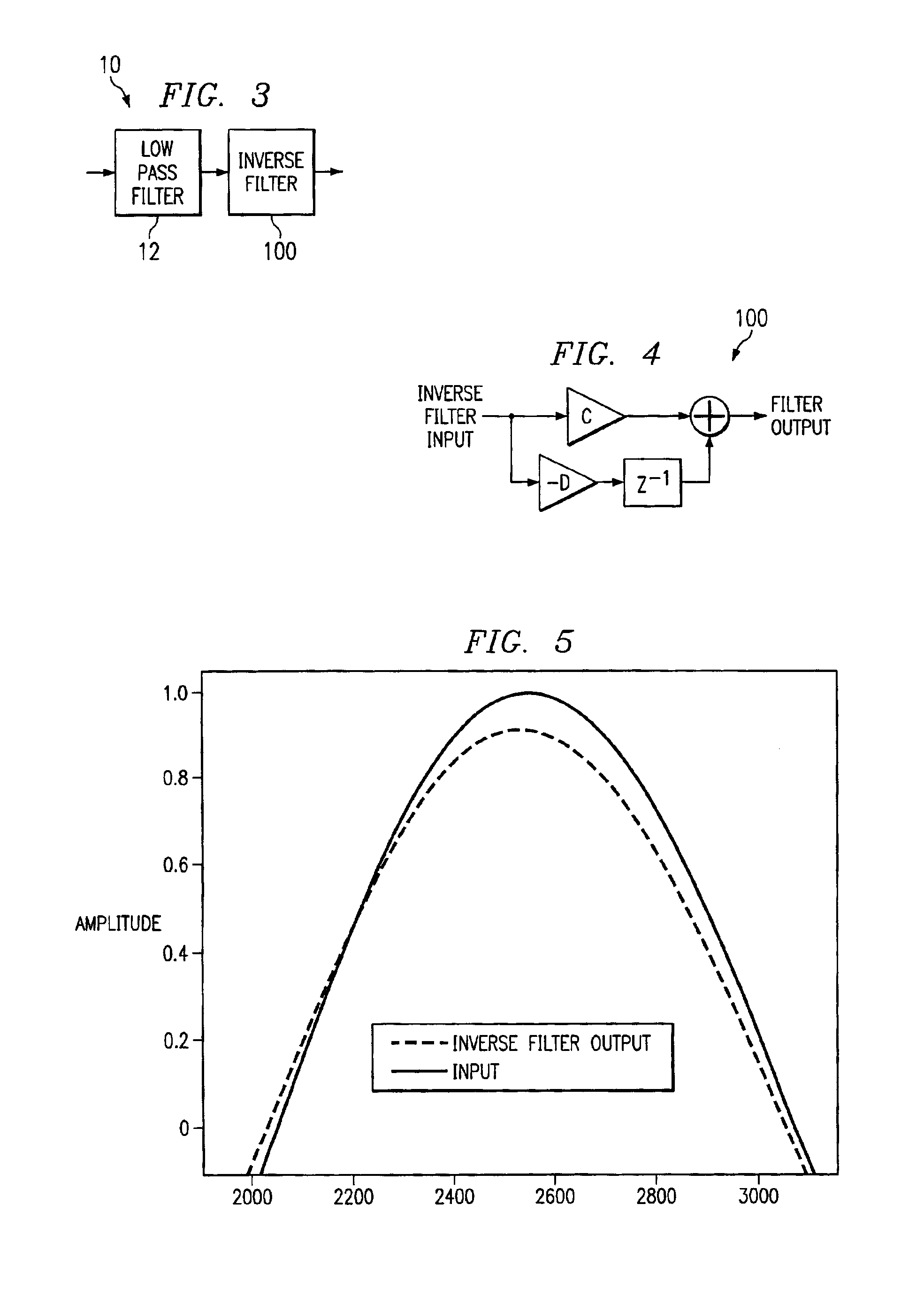
[0007]The present invention is directed to a simple, power efficient and inexpensive digital compensation scheme for reducing delay in a digital impedance matching circuit to improve return loss. The scheme employs a digital filter to compensate for the absolute sampling and digital delays associated with a digital impedance matching circuit. The digital filter is based on the low-pass function of a DAC response, and can easily be modified to correct for not only the DAC response delay, but also other delays in the digital impedance matching circuit. This digital filter is very simple to implement and can add or subtract delays from the overall system.

Problems solved by technology

Digital implementations of impedance matching networks are problematic due to the delay(s) through the digital processor(s).
These delays cause a phase difference between the incident and synthesized signals which results in an amplitude difference that worsens the Return Loss.
This problem is generally alleviated by using a faster, but more costly and higher power consuming digital converter and processor.

Method used


Image

  • Compensation scheme for reducing delay in a digital impedance matching circuit to improve return loss
  • Compensation scheme for reducing delay in a digital impedance matching circuit to improve return loss
  • Compensation scheme for reducing delay in a digital impedance matching circuit to improve return loss

Examples


Embodiment Construction

[0025]The embodiments described herein below are directed to techniques including structures and methods for correcting the phase delay through a digital impedance matching system. These techniques allow digital circuits to synthesize a more accurate matching impedance to improve return loss. It will also be shown that the return loss of a system is dependent on both the amplitude matching and also the delay in the system. Even if the amplitude of the return signal is matched correctly to the incident signal therefore, a significant delay in the signal will cause a significant degradation in the return loss.

[0026]The return loss can be affected by a phase difference between the incident and reflected voltages, which translates to reactive differences in the line impedance and the matching impedance. For a given return loss then, there will be a specific phase difference. The amplitude variation and the phase variation must be kept to a minimum on all components to ensure an effectiv...


PUM


Abstract

A simple, power efficient and inexpensive digital compensation scheme for reducing delay in a digital impedance matching circuit to improve return loss. The scheme employs a digital filter to compensate for the absolute sampling and digital delays associated with a digital impedance matching circuit. The digital filter is based on the low-pass function of a DAC response, and can easily be modified to correct for not only the DAC response delay, but also other delays in the digital impedance matching circuit. The digital filter is very simple to implement and can add or subtract delays from the overall system.

Description

BACKGROUND OF THE INVENTION[0001]1. Field of the Invention[0002]This invention relates generally to impedance matching circuits, and more particularly, to a digital compensation scheme for reducing delay in a digital impedance matching circuit to improve return loss.[0003]2. Description of the Prior Art[0004]Impedance matching is a critical function for telephone equipment. The trend for telephone line impedance matching has been from hybrid transformer to discrete opamp circuits, to integrated analog / digital implementations used to synthesize the required matching impedance.[0005]Digital implementations of impedance matching networks are problematic due to the delay(s) through the digital processor(s). These delays cause a phase difference between the incident and synthesized signals which results in an amplitude difference that worsens the Return Loss. This problem is generally alleviated by using a faster, but more costly and higher power consuming digital converter and processor...

Claims


Application Information

Patent Timeline
Patent Type & Authority Patents(United States)
IPC IPC(8): H03H17/00
CPCH03H17/0045
Inventor CHAN, WING K.NABICHT, JOSEPH T.
Owner TEXAS INSTR INC
Learn More