Pinch roll unit

a technology of rolling unit and rolling pin, which is applied in the direction of measuring device, roll speed control device, manufacturing tool, etc., can solve the problems of rolling against the product surface, particularly acute problems, and slippage of rolls

Inactive Publication Date: 2005-07-26
PRIMETALS TECH USA
View PDF12 Cites 20 Cited by
  • Summary
  • Abstract
  • Description
  • Claims
  • Application Information

AI Technical Summary

Problems solved by technology

Marking can result from excessive pinching force, or by an imbalance of pinching force and driving torque resulting in slippage of the rolls against the product surface.
The latter have proven to be problematical due to fluctuations in the pressure of compressed air normally available in rolling mills, and the relatively slow reaction times attributable largely to solenoid valve dead times, cylinder closing times, and the stroke distance of the pistons.
Such problems are particularly acute in high speed rolling environments, e.g., in rod mills where product delivery speeds now routinely exceed 100 m / sec.

Method used


Image

  • Pinch roll unit
  • Pinch roll unit
  • Pinch roll unit

Examples


Embodiment Construction

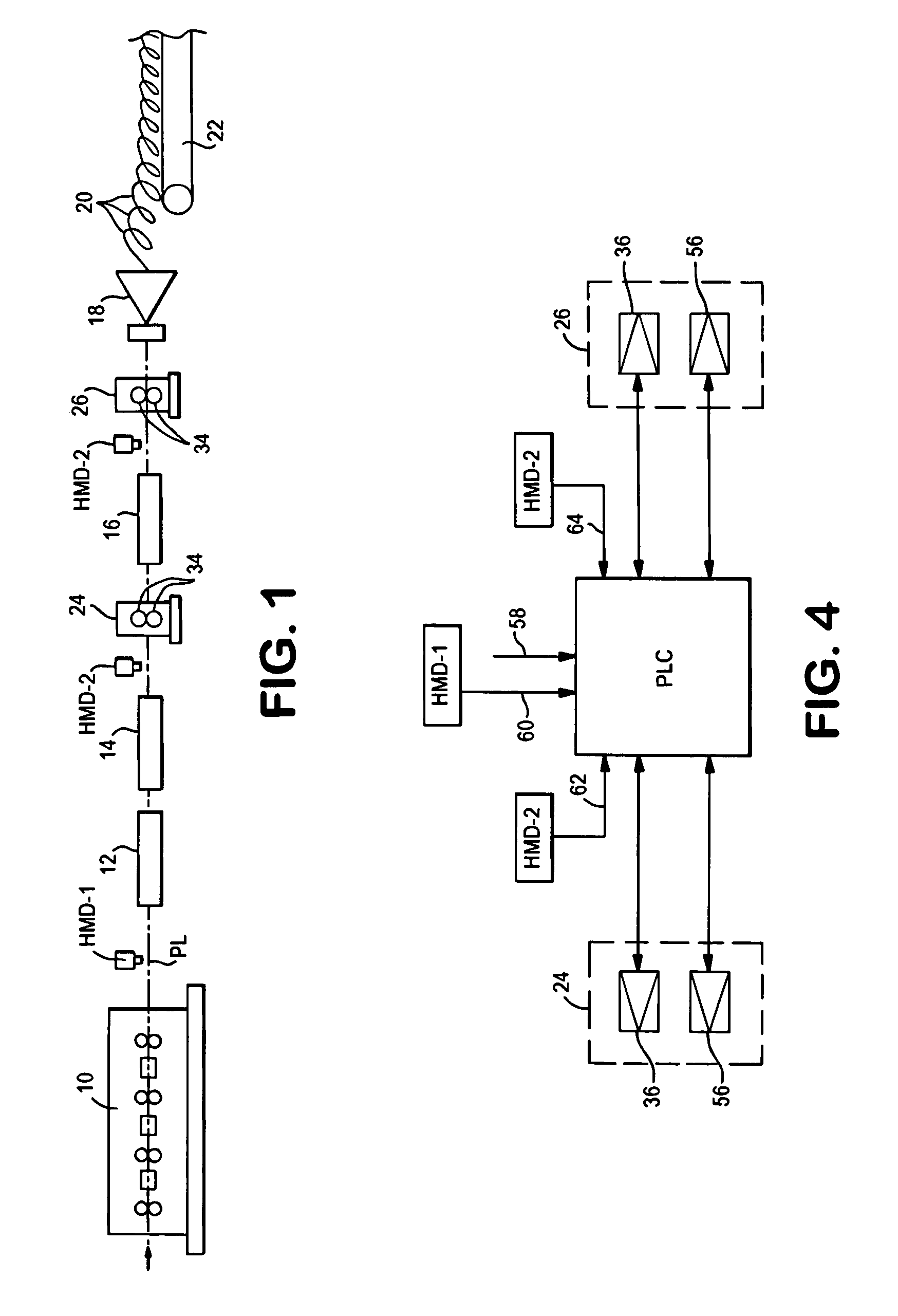
[0018]With reference initially to FIG. 1, an exemplary delivery end of a high speed rod mill is shown comprising a finishing block 10 of the type disclosed, for example, in U.S. Pat. No. Re. 28, 107. The hot rolled rod is propelled from the finishing block along the mill pass line PL at speeds typically exceeding 100 m / sec. The rod is cooled sequentially in water boxes, 12, 14 and 16 before being directed to a laying head 18. The laying head forms the rod into a continuous series of rings 20 which are deposited in an offset pattern on a cooling conveyor 22. The cooling conveyor delivers the rings to a reforming station (not shown) for collection into coils.

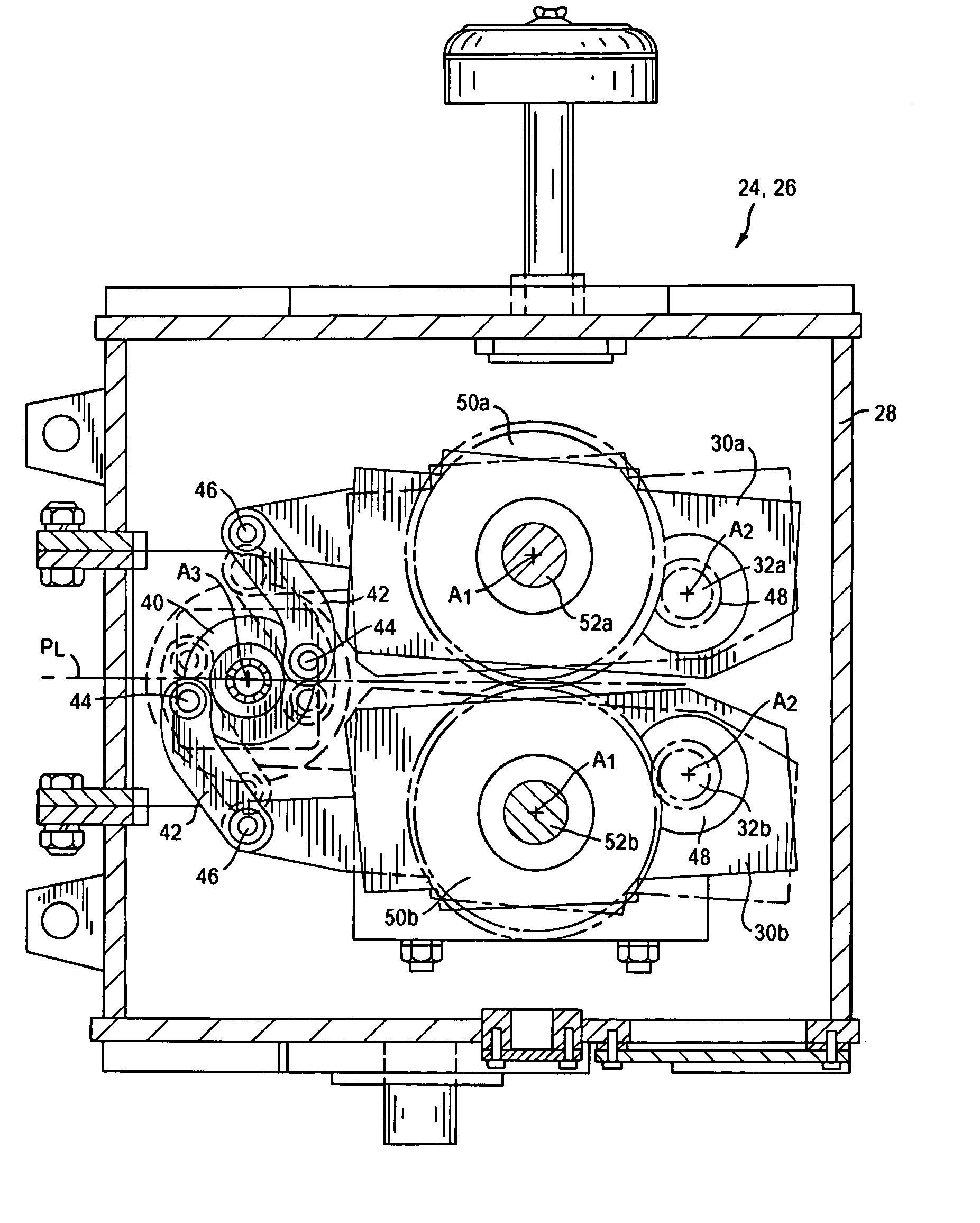
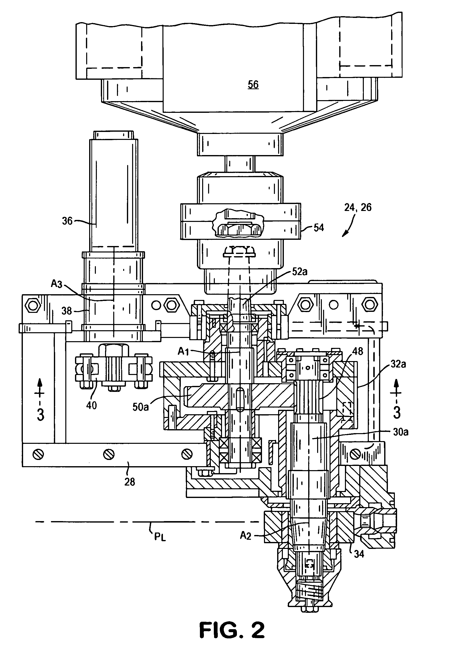
[0019]Pinch roll units 24 and 26 in accordance with the present invention are positioned along the mill pass line PL. Pinch roll unit 24 serves mainly in a driving mode to propel the product forwardly and to insure its passage through the last water box 16. Pinch roll unit 26 operates in either a breaking mode to slow the tail end...


PUM

PropertyMeasurementUnit
speedsaaaaaaaaaa
distanceaaaaaaaaaa
pressureaaaaaaaaaa

Abstract

A pinch roll unit for either propelling or retarding a product moving along the pass line of a rolling mill comprises a pair of levers mounted for rotation about parallel first axes. Roll shafts are carried by the levers with each roll shaft being journalled for rotation about a second axis parallel to the first axis of its respective lever. Pinch rolls are carried by the roll shafts and are positioned to define a gap therebetween for receiving the product. An electrically powered first motor operates via a linkage to rotate the levers about the first axes and to move the pinch rolls between open positions spaced from the product, and closed positions contacting and gripping the product therebetween. An electrically powered second motor rotatably drives the pinch rolls.

Description

BACKGROUND OF THE INVENTION[0001]1. Field of the Invention[0002]This invention relates generally to hot rolling mills of the type producing bar and rod products, and is concerned in particular with improvements in the pinch roll units and associated controls employed to propel and / or retard the movement of such products at various places along the mill pass line.[0003]2. The Prior Art[0004]Pinch roll units are conventionally employed in rod mills to propel smaller diameter products through water boxes, and to propel larger diameter products through the laying heads. Alternatively, pinch roll units can be employed to retard and brake the movement of bar products being directed to cooling beds, and to prevent the tail ends of rod products from accelerating after they leave the last mill stand and before they arrive at the laying heads.[0005]Pinch roll closure must be precisely timed to achieve the desired function, and the pinching force and torque exerted by the pinch rolls must be c...

Claims


Application Information

Patent Timeline
Patent Type & Authority Patents(United States)
IPC IPC(8): B21B31/28B21B39/00B21B31/16B21B37/58B21B39/02B21B37/46B21B39/06B21B38/10B21B45/02B21B38/00B21B39/08B21B1/16B21B1/18B21B41/12B21C47/34
CPCB21B31/28B21B37/58B21B39/006B21B1/18B21B37/46B21B38/105B21B2275/06B21B39/06B21B39/08B21B2045/0236B21B2203/22B21B2273/18B21B39/088
Inventor SHORE, T. MICHAELRICHES, PAUL B.LING, YUNPUCHOVSKY, MELICHER
Owner PRIMETALS TECH USA
Why Eureka
Try Eureka