
Exposure apparatus

a technology of exposure apparatus and wafer, which is applied in the direction of lighting and heating apparatus, drying machines with progressive movements, instruments, etc., can solve the problems of increasing the labor cost of maintenance and running, increasing the resistance deterioration of the wafer, and increasing the contaminated chemical filter. , to achieve the effect of stable exposure process, accurate control of pressure, and high accuracy

Inactive Publication Date: 2005-08-02
NIKON CORP
View PDF18 Cites 20 Cited by
  • Summary
  • Abstract
  • Description
  • Claims
  • Application Information

AI Technical Summary

Benefits of technology

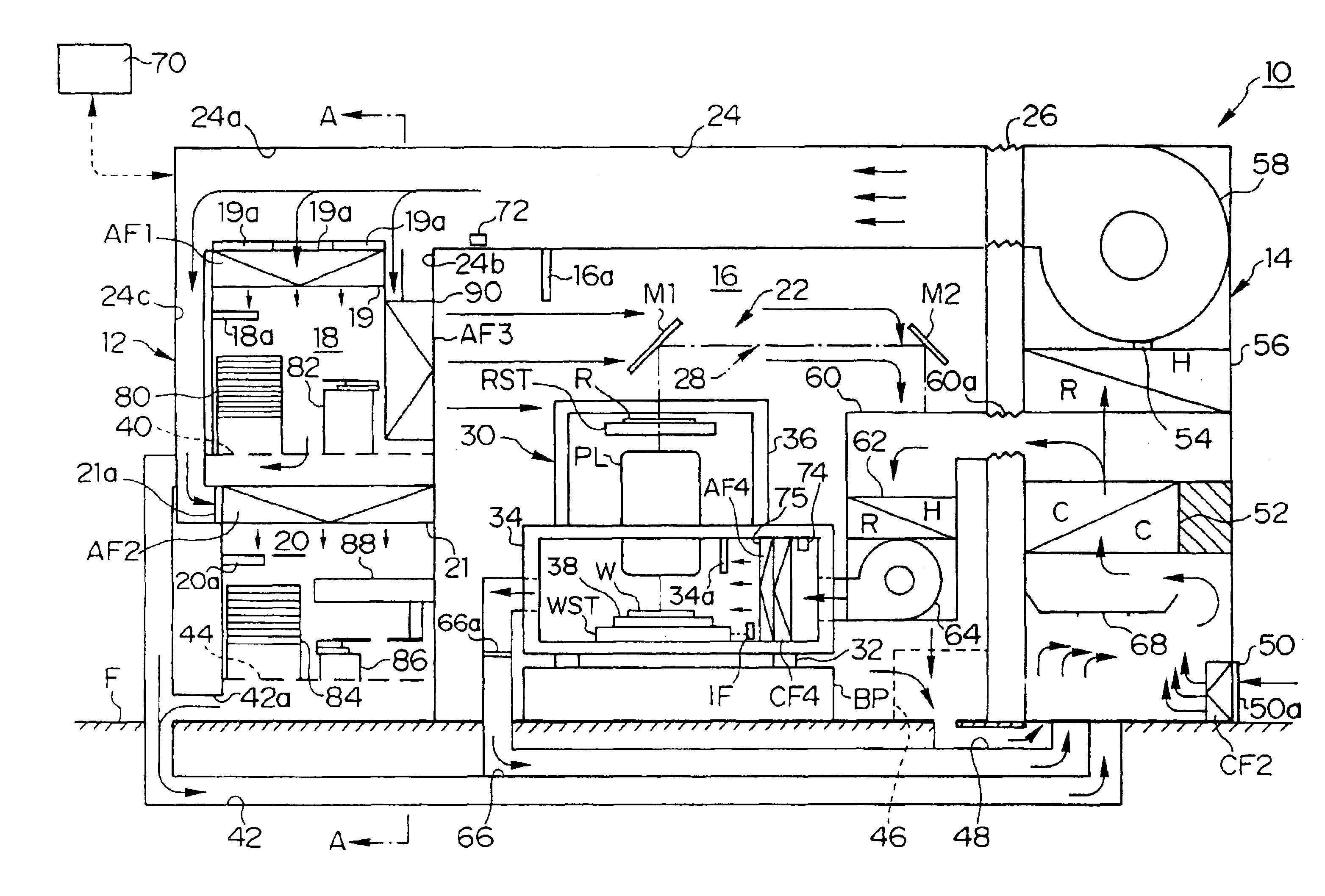
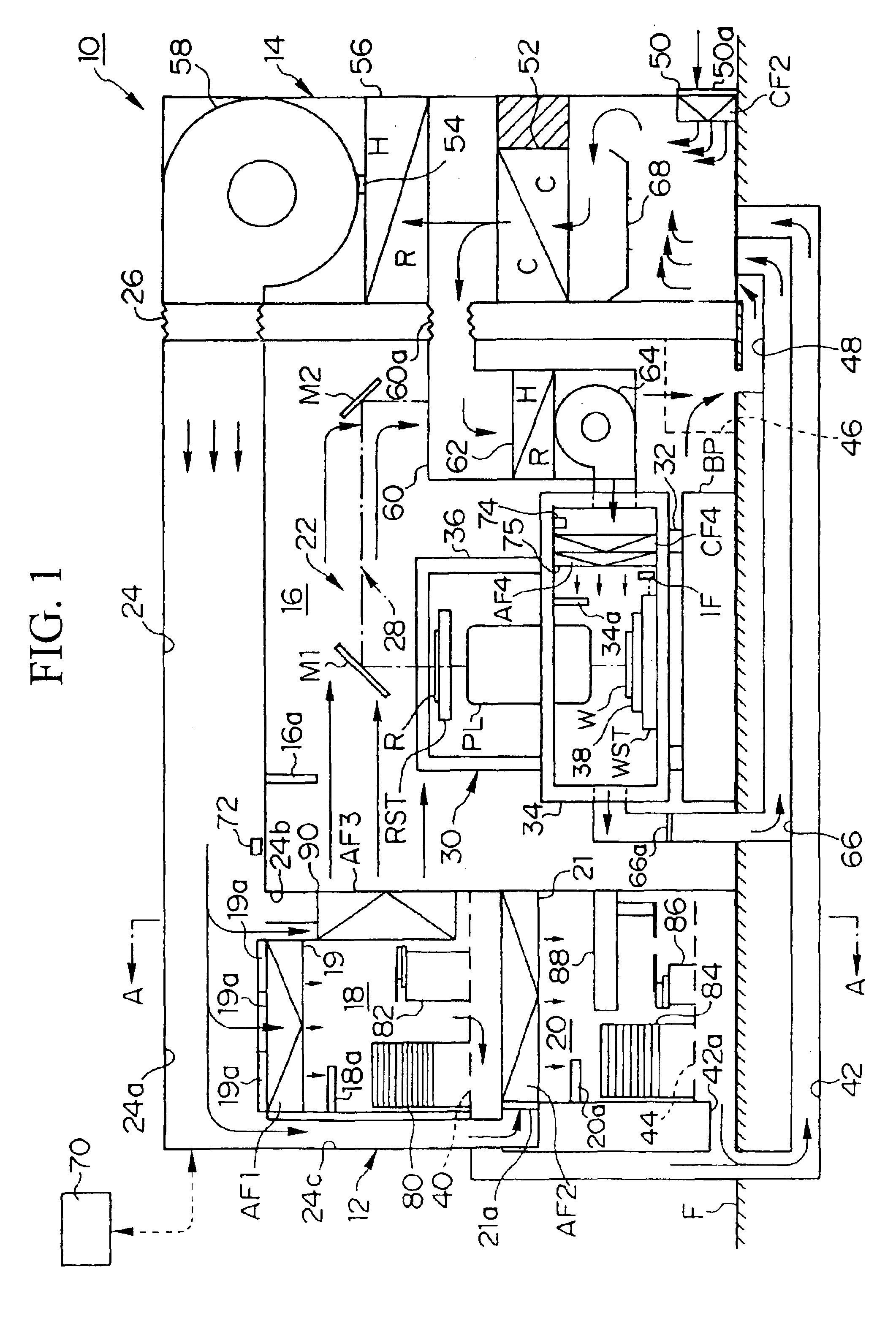
[0010]The present invention is achieved in consideration of the above situation, and its purpose includes to provide an exposure apparatus capable of performing a stable exposure process with high accuracy by accurately controlling the pressure inside a chamber having a plurality of air-conditioning chambers.
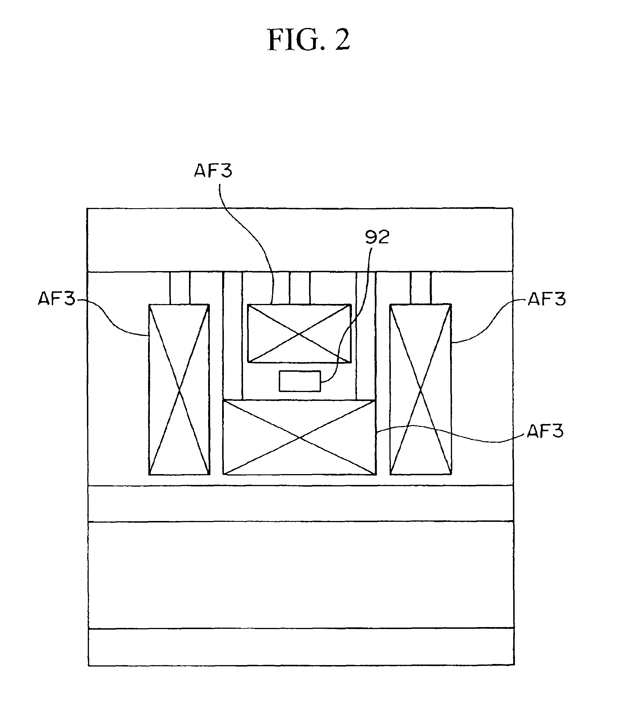
[0013]According to the present invention, it is possible to allocate the pressure detection device (16a, 18a, 20a, and 34a) which detects pressure information (for example, the pressure of each of the air-conditioning chambers or the difference in pressure of each of the air-conditioning chambers with respect to a reference pressure) relating to the plurality of the air-conditioning chambers (16, 18, 20, and 34), and to accurately control the pressure based on the detection results. Since the cleanliness for the substrate (W) or the space for optical passage of an exposure light may be maintained to be high by accurately carrying out the pressure control, it becomes possible to prevent deterioration of resist when the resist is applied on the wafer (W) or the attenuation in the amount of exposure light in the optical path space. Accordingly, an accurate exposure process can be performed.
[0017]According to the present invention, since turbulence due to gas flow is reduced and the generation of air fluctuation is prevented by setting the pressure of the column chamber (34) in which the substrate (W) is placed for the longest period in the chamber (12), to be higher than the pressure of the other air-conditioning chambers (16, 18, and 20), it becomes possible to improve the measurement accuracy of, for example, a position detection system (an interferometer, etc.) which detects positional information of a mask stage or a substrate stage, a focus point detection system which detects a relative positional relationship between a field of a projection optical system and a substrate, and various measuring systems, such as an alignment system which detects a mark on a substrate, etc. Moreover, since contaminants can be prevented from flowing into the column chamber (34), it becomes possible to prevent the deterioration of resist when the resist is applied on the substrate (W). Furthermore, since no contaminants flow into the column chamber (34) which is the space for the optical path of an exposure light, it becomes possible to prevent the attenuation in the amount of the exposure light. Accordingly, since the cleanliness of the substrate (W) or the space of optical path for the exposure light can be maintained to be high by increasing the pressure of the column (34) with respect to the other air-conditioning chambers (16, 18, and 20), it becomes possible to carry out an accurate exposure process. Also, by setting the pressure of the substrate transferring system accommodating chamber (20) in which the substrate (W) is placed for the second longest period after the column chamber (34), to be highest after the column chamber (34) among the other air-conditioning chambers (16 and 18), it becomes possible to prevent contaminants from flowing into the substrate transferring system accommodating chamber (20). Accordingly, it becomes possible to prevent resist deterioration when the resist is applied onto the substrate (W). Note that the above-mentioned exposure chamber may accommodated the whole main body of the exposure chamber, or it may accommodate only a part thereof. Also, the space of the air-conditioning chambers may be clearly defined by housings, etc., or it can be a space to which a gas, the temperature etc., of which is controlled, is simply supplied without using housings, partitioning plates, and so forth.

Problems solved by technology

In the overall air-conditioning system for the exposure chamber, on the other hand, labor for maintenance and running cost will increase if a chemical filter is used since a large amount of air is required for the overall air-conditioning system and hence the chemical filter is quickly contaminated and needs to be frequently replaced.
Thus, if a gas flows into the main column or the wafer loader chamber in which the air-conditioning is performed using a chemical filter, from the exposure chamber in which the air-conditioning is carried out without using a chemical filter, problems such as increase in resist deterioration of the wafer may be caused.
Also, if contaminants are present in an optical path space, which is a space through which the exposure light passes, problems may be caused in that an exposure process cannot be performed with high accuracy due to factors such as the exposure light being attenuated and cannot reach the wafer with a sufficient strength, or unevenness of illuminance occurs on the wafer.
However, since the difference in pressure between each of the air-conditioning chambers inside the chamber is very small, a large difference in pressure may be caused and a gas flow (air current) may be generated among each of the air-conditioning chambers and an appropriate air-conditioning cannot be performed unless the pressures are accurately controlled.
Accordingly, problems may be generated so that it is not possible to achieve an exposure process with high accuracy and so that the accuracy in measurement of optical measuring devices (a laser interferometer, etc.) is reduced.
As explained above, although there is a danger that the resist of the wafers may be deteriorated, the cleanliness of the optical path space for the exposure light cannot be maintained to a predetermined level, and a flow is caused among the air-conditioning chambers and a stable exposure process cannot be achieved, unless the pressure is accurately controlled inside the chamber having a plurality of air-conditioning chambers, a strict pressure control is not conventionally carried out.

Method used


Image

  • Exposure apparatus
  • Exposure apparatus
  • Exposure apparatus

Examples


first embodiment

[0124]According to the exposure apparatus of the present invention, it becomes possible to detect the pressure of each of the air-conditioning chambers by placing a pressure detection device which detects the pressure of the air-conditioning chamber, in each of the plurality of the air-conditioning chambers provided in a chamber, and to accurately control the pressure based on the detection results. Since the cleanliness of the substrate or the optical path space of the exposure light may be maintained at high level, it becomes possible to prevent the deterioration of resist when the resist is applied on the substrate and the attenuation of the exposure light in the optical path space. Accordingly, an exposure process can be carried out with high accuracy.

second embodiment

[0125]According to the exposure apparatus of the present invention, since the pressure control device which adjust the pressure of each of the air-conditioning chambers is provided and the pressure control device adjusts the pressure based on the detection results of the pressure detection device so that each of the plurality of the air-conditioning chambers has a predetermined pressure difference, it becomes possible to control the pressure, for example, so as to generate a predetermined pressure difference in a degree not causing a large flow (air current) between the air-conditioning chambers. Accordingly, the pressure may be adjusted with high accuracy.

[0126]According to the exposure apparatus of the third and fourth embodiments of the present invention, since the pressure control device adjusts the pressure by controlling at least one of a gas supplying amount and a gas exhaust amount with respect to each of the air-conditioning chambers, and the device includes a flow controll...

fifth embodiment

[0127]According to the exposure apparatus of the present invention, since the pressure of the column chamber which accommodates the exposure stage on which the substrate is placed for the longest period in the exposure apparatus is set to be higher than the other air-conditioning chambers, contaminants present outside do not flow into the column chamber. Accordingly, it becomes possible to prevent the deterioration of the resist when the resist is applied on the substrate. Also, since the column chamber functions as the optical path space of the exposure light, it becomes possible to prevent the attenuation in the intensity of the exposure light and the generation of uneven illuminance. Accordingly, an exposure process of high accuracy can be carried out.

[0128]According to the exposure apparatus of the sixth to tenth embodiments of the present invention, since the pressure of the column chamber in which the substrate is placed for the longest period in the chamber is set to be highe...


PUM

PropertyMeasurementUnit
pressureaaaaaaaaaa
pressureaaaaaaaaaa
output wavelengthaaaaaaaaaa

Abstract

An exposure apparatus is provided for performing exposure processes with high accuracy by accurately performing pressure control inside a chamber having a plurality of air-conditioning chambers. The inside of the main chamber which accommodates the exposure apparatus is divided into a plurality of air-conditioning chambers, and a pressure detection device which detects the pressure is provided with each of the plurality of air-conditioning chambers. Also, among the plurality of the air-conditioning chambers, the pressure inside a main column which accommodates an exposure stage on which a wafer in mounted and subjected to an exposure process, is set to be higher than the pressure of the other air-conditioning chambers based on detection results obtained from the pressure detection devices.

Description

[0001]This is a Continuation of Application No. PCT / JP01 / 11634 filed Dec. 28, 2001, which claims the benefit of Japanese Patent Application No. 2000-402273 filed Dec. 28, 2000. The entire disclosure of the prior applications is hereby incorporated by reference herein in its entirety.TECHNICAL FIELD[0002]The present invention relates to an exposure apparatus used for exposing a pattern image onto a substrate.[0003]This application is based on Japanese Patent Application No. 2000-402273, the content of which is incorporated herein by reference.BACKGROUND ART[0004]Various exposure apparatuses have been employed when semiconductor elements, thin film magnetic heads, or liquid crystal display elements are manufactured using photolithographic processes, however, in general, an apparatus is used which projects a pattern image formed on a photomask or reticle (hereinafter referred to as a “reticle”) onto a substrate such as a wafer or a glass plate (hereinafter referred to as a “wafer”), th...

Claims


Application Information

Patent Timeline
Patent Type & Authority Patents(United States)
IPC IPC(8): G03F7/20
CPCG03F7/70858G03F7/70883
Inventor TSUJI, TOSHIHIKONAGAHASHI, YOSHITOMOKIMURA, TAKAAKITAKAGI, SHINICHI
Owner NIKON CORP
Learn More